

Compound Lenses
Compound lenses, consisting of two or more individual lenses mounted together, play a critical role in modern optical systems by combining various optical properties to achieve desired imaging results. Unlike single lenses, which can only offer limited correction and magnification, compound lenses are designed to correct aberrations, enhance image quality, and achieve higher magnifications with greater precision. These multi-lens systems are integral in a range of real-world applications, from sophisticated microscopes and telescopes to everyday devices like eyeglasses and cameras. By understanding how compound lenses work, one can appreciate their impact on clear vision, detailed imaging, and advanced optical instruments that drive innovations in science, photography, and visual technologies. In this article, we will discuss the way of a combination of two lenses, formulas and some solved examples for better understanding.
This Story also Contains
- Combination of the Thin Lens in Contact
- Lenses at a Distance
- Position of the Equivalent Lens
- Solved Example Based on Compound Lenses
- Summary
Combination of the Thin Lens in Contact
When multiple thin lenses are placed in contact with each other, their combined optical effect can be determined using principles of lens combinations. Each lens contributes to the overall optical power of the system, and the resulting image formation is a cumulative effect of all lenses. Understanding how to calculate the combined focal length and power of such lens systems is crucial for designing optical devices like cameras, microscopes, and corrective lenses.
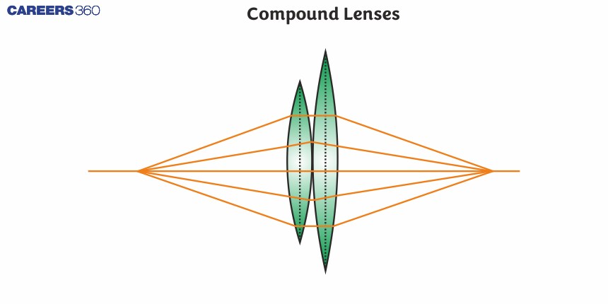
Till now we have discussed single lenses, but what happens when two or more than two lenses are combined together. For this let us consider two lenses A and B of focal length f1 and f2 placed in contact with each other. Let the object be placed at a point O beyond the focus of the first lens A (See the figure).
The first lens produces an image at I1. Now the image at I1 is real but it serves as a virtual object for the second lens B. The lens B produces the final image at I. Since the lenses are thin, we assume the optical centres of the lenses to be coincident. Let this central point be denoted by P.
So for the lens A
$\frac{1}{v_1}-\frac{1}{u}=\frac{1}{f_1}$;
Similarly for lens B
$\frac{1}{v}-\frac{1}{v_1}=\frac{1}{f_2}$
Adding both the equation, we get
$\frac{1}{v}-\frac{1}{u}=\frac{1}{f_1}+\frac{1}{f_2} \cdots (1)$
Now, let us assume two systems equivalent to a single lens of focal length f, we have
$\frac{1}{v}-\frac{1}{u}=\frac{1}{f} \ldots (2) $
So from (1) and (2), we can conclude that the focal length after the combination of two thin lenses, we get
$\frac{1}{f}=\frac{1}{f_1}+\frac{1}{f_2}$
Similarly by combining any number of thin lenses in contact. we can get
$\frac{1}{f}=\frac{1}{f_1}+\frac{1}{f_2}+\frac{1}{f_3} \quad \cdots$
In terms of Power, we can write this equation as
$P=P_1+P_2+P_3+\ldots$
Here P is the net power of the lens combination. Note that the sum is an algebraic sum of individual powers, so the power may be positive or negative because it may be a combination of both concave or convex lenses. So some of the terms on the right side may be positive (for convex lenses) and some negative (for concave lenses).
In terms of magnification, we can write the net magnification as
$m=m_1 \cdot m_2, m_3 \ldots$
As we know in combination with lenses, the image of the first lens is the object of the second lens. So the magnification due to the combination of lenses is the multiplication of individual magnification.
The combination of lenses is needed in lenses for cameras, microscopes, telescopes and other optical instruments.
Lenses at a Distance
When two thin lenses are separated by a distance,it is equivalent to a thick lens, but not equivalent to a single thin lens. Now let us take a special case in which the object is placed at infinity, so the combination may be replaced by a single thin lens. We shall now derive the position and focal length of the equivalent lens in this special case. To start with, let us derive an expression for the angle of deviation of a ray when it passes through a lens.

Let 0 be a point object on the principal axis of a lens. Let OA be an incident ray on the lens at point A which is at a height h above the optical centre. It is deviated through an angle $\delta$ and comes out along AI. It strikes the principal axis at I where the image is formed.
Let $\angle A O P=\alpha$ and $\angle A I P=\beta$. By triangle $O A I$,
By exterior angle property $\Rightarrow \delta=\alpha+\beta$
If the height h is very small as compared to the PI and PO, then they $\alpha, \beta$ will be very small,
So we can write,
$\begin{gathered}\alpha=\tan \alpha=h / O P \text { and } \beta=\tan \beta=h / P I . \\ \delta=\frac{h}{P O}+\frac{h}{P I}\end{gathered}$
Now by sign convention, we can write that the PO = -u and PI = v, So the above equation can be written as -
$\begin{gathered}\delta=h\left(\frac{1}{v}-\frac{1}{u}\right) \\ \delta=\frac{h}{f}\end{gathered}$
Now let us consider two thin lenses are placed coaxially at a separation d. The incident ray AB and the emergent ray CD intersect at a point named E. The perpendicular from E to the principal axis falls at P. The equivalent lens should be placed at this position P. A ray ABE going parallel to the principal axis will go through the equivalent lens and emerge along ECD. The angle of deviation is
$
\delta=\delta_1+\delta_2
$
(From the exterior angle property of the triangle $B E C$ )
The focal length of the equivalent lens is $F=P D$,

Using above equation $\delta_1=\frac{h_1}{f_1}, \quad \delta_2=\frac{h_2}{f_2}$ and $\delta=\frac{h_1}{F}$
As $\delta=\delta_1+\delta_2$
$
\frac{h_1}{F}=\frac{h_1}{f_1}+\frac{h_2}{f_2}
$
Now,
$
\begin{gathered}
h_1-h_2=P_2 G-P_2 C=C G \\
=B G \tan \delta_1=B G \delta_1 \\
\text { or, } h_1-h_2=d \frac{h_1}{f_1}
\end{gathered}
$
Thus, by,
$
\begin{aligned}
\frac{h_1}{F} & =\frac{h_1}{f_1}+\frac{h_1}{f_2}-\frac{d\left(h_1 / f_1\right)}{f_2} \\
\text { or, } \frac{1}{F} & =\frac{1}{f_1}+\frac{1}{f_2}-\frac{d}{f_1 f_2}
\end{aligned}
$
Position of the Equivalent Lens
$\begin{aligned} \text { We have, } & P P_2=E G \\ = & G C \cot \delta \\ = & \frac{h_1-h_2}{\tan \delta} \\ h_1-h_2=\frac{d h_1}{f_1} \cdot & \text { Also, } \delta=\frac{h_1}{F} \text { so that } \\ P P_2= & \left(\frac{d h_1}{f_1}\right)\left(\frac{F}{h_1}\right)=\frac{d F}{f_1}\end{aligned}$
Thus, the equivalent lens is to be placed at a distance $\frac{d \cdot F}{f_1}$ behind the second lens.
Note - Both the above relation are true only for the special case of the parallel incident beam. If the object is at a finite distance, one should not use the above equations.
Solved Example Based on Compound Lenses
Example 1: An object is at a distance of 10 cm from a mirror, and an image of the object is at a distance of 30 cm from the mirror from the same side as the object. Then the nature of the mirror and its power is
1) Concave, $\frac{40}{3} \mathrm{D}$
2) Convex, $\frac{40}{3} \mathrm{D}$
3) Concave, $\frac{20}{3} \mathrm{D}$
4) Convex, $\frac{20}{3} \mathrm{D}$
Solution:
Optical power of a mirror
$P=-\frac{1}{f}$
wherein
$f=$ focal length with a sign and is in meters unit of power $=$ diopter
$
\begin{aligned}
& \frac{1}{f}=\frac{1}{v}+\frac{1}{u} \\
& \mathrm{u}=-10 \mathrm{~cm}, \mathrm{v}=-30 \mathrm{~cm} \\
& \frac{1}{f}=\frac{-1}{10}-\frac{1}{30}=-\frac{4}{30}
\end{aligned}
$
$\therefore$ mirror is concave
$
p=\frac{-100}{f} D=\frac{100}{7.5} D=\frac{40}{3} D
$
Hence, the answer is the option (1).
Example 2: A convergent doublet of separated lenses, corrected for spherical aberration, has a resultant focal length of 10 cm. The separation between the two lenses is 2 cm. The focal lengths of the component lenses are :
1) 10 cm, 12 cm
2) 12 cm, 14 cm
3) 16 cm, 18 cm
4) 18 cm, 20 cm
Solution:
$\begin{aligned} & \frac{1}{f}=\frac{1}{f_1}+\frac{1}{f_2}-\frac{d}{f_1 f_2} \\ & \therefore \frac{1}{10}=\frac{f_1+f_2-2}{f_1 f_2} \text { or } f_1+f_2-2=\frac{f_1 f_2}{10}\end{aligned}$
By trial and error method
Putting all option values one by one
For A we get f1 = 10 cm which is given
Hence, the answer is the option (1).
Example 3: One plano-convex and one plano-concave lens of the same radius of curvature 'R' but of different materials are joined side by side as shown in the figure. If the refractive index of the material of 1 is $\mu_1$ and that of 2 is $\mu_2$, then the focal length of the combination is:

1) $\frac{R}{\mu_1-\mu_2}$
2) $\frac{2 R}{\mu_1-\mu_2}$
3) $\frac{R}{2\left(\mu_1-\mu_2\right)}$
4) $\frac{R}{2-\left(\mu_1-\mu_2\right)}$
Solution:
For lens 1
$
\frac{1}{f_1}=\left(\mu_1-1\right)\left(\frac{1}{\infty}-\frac{1}{-R}\right)
$
For lens 2
$
\begin{aligned}
\frac{1}{f_2} & =\left(\mu_2-1\right)\left(\frac{1}{-R}-\frac{1}{\infty}\right) \\
\frac{1}{f_e q} & =\frac{1}{f_1}+\frac{1}{f_2} \\
& =\frac{\mu_1-1}{R}+\frac{1-\mu_2}{R} \\
f_{e q} & =\frac{R}{\mu_1-\mu_2}
\end{aligned}
$
Hence, the answer is the option (1).
Example 4: Two identical thin biconvex lenses of focal length 15 cm and refractive index 1.5 are in contact with each other. The space between the lenses is filled with a liquid of refractive index 1.25. The focal length of the combination is ____ cm.
1) 10
2) 5
3) 7
4) 8
Solution:

$
\begin{aligned}
& \frac{1}{\mathrm{f}}=(\mu-1)\left(\frac{2}{\mathrm{R}}\right)=\frac{1}{\mathrm{R}}=\frac{1}{15 \mathrm{~cm}} \\
& \mathrm{R}=15 \mathrm{~cm}
\end{aligned}
$
Let the focal length of the concave lens be $f^{\prime}$
$
\begin{aligned}
& \frac{1}{\mathrm{f}^{\prime}}=(\mu-1)\left(\frac{-2}{\mathrm{R}}\right)=\frac{-1}{30 \mathrm{~cm}} \\
& \mathrm{f}^{\prime}=-30 \mathrm{~cm} \\
& \frac{1}{f_{e f f}}=\frac{2}{f}+\frac{1}{f^{\prime}}=\frac{2}{15}-\frac{1}{30}=\frac{1}{10 \mathrm{~cm}}
\end{aligned}
$
The focal length of the combination is $\mathrm{10\, cm}$
Hence, the answer is the option (1).
Example 5: Curved surfaces of a plano-convex lens of refractive index $\mu_{1}$ and a plano-concave lens of refractive index $\mu_{2}$ have equal radius of curvature as shown in figure. Find the ratio of radius of curvature to the focal length of the combined lenses.

1) $\frac{1}{\mu_2-\mu_1}$
2) $\frac{1}{\mu_1-\mu_2}$
3) $\mu_1-\mu_2$
4) $\mu_2-\mu_1$
Solution:

$\begin{aligned} & \frac{1}{f_{e q}}=\frac{1}{f_1}+\frac{1}{f_2} \\ & \frac{1}{f_1}=\left(\mu_1-1\right)\left(\frac{1}{\infty}-\frac{1}{(-R)}\right)=\frac{\left(\mu_1-1\right)}{R} \\ & \frac{1}{f_2}=\left(\mu_2-1\right)\left(\frac{1}{-R}-\frac{1}{\infty}\right)=\frac{\left(\mu_2-1\right)}{R} \\ & =\frac{\left(\mu_1-1\right)}{R}-\frac{\left(\mu_2-1\right)}{R} \\ & \frac{1}{f_{c q}}=\frac{\mu_1-\mu_2}{R} \\ & \Rightarrow \frac{R}{f_{e q}}=\mu_1-\mu_2 \\ & \end{aligned}$
Hence, the answer is the option (3).
Summary
Compound lenses, consisting of two or more thin lenses placed in contact, allow for greater flexibility in optical design by combining their individual powers. The overall focal length of such systems is the reciprocal of the sum of the individual lens powers, which simplifies the design of optical instruments like microscopes and cameras. Additionally, understanding these combinations helps in practical applications such as eyeglasses and camera lenses, where multiple lenses are used to correct vision or enhance image quality. Solved examples demonstrate how to calculate the focal length and power of combined lenses, emphasizing their importance in precise optical applications.
