

To Find the Focal Length of a Concave Lens Using Convex Lens
A multimeter is a versatile tool used for measuring electrical properties and diagnosing components in electronic circuits. By using a multimeter, you can identify various components, check their functionality, and distinguish between different types of transistors and diodes. For a transistor, you can determine the base lead and distinguish between NPN and PNP types. When testing diodes and LEDs, a multimeter helps verify their unidirectional current flow. Additionally, it can be used to test other electronic components by measuring their resistance, continuity, or other relevant properties.
This Story also Contains
- Aim
- Apparatus
- Theory
- Procedure
- To Possibilities Arise 1. The resistance is high in both cases in Figure (a) and Figure (b). Then proceed as explained further in figure (c), (d), (d), (e) and (f) and locate the base leg and the type of transistor n-p-n or p-n-p.
- Identifying the Emitter and Collector leads (Having Known the Base)
- Case of a junction Diode
- Some Solved Examples
- Solution:
- Summary
Aim
To use a multimeter to
(a) identify the base of the transistor
(b) distinguish between NPN and PNP type transistors.
(c) see the unidirectional flow of current in the case of a diode and an LED.
(d) check whether a given electronic component (e.g., diode, transistor or IC) is in working order.
Apparatus
A multimeter, transistors, NPN and PNP, an IC, a diode and an LED.
Theory
1. A transistor is a three-terminal device. It can be regarded as a combination of two junction diodes joined in an opposite manner such that the middle part is common to both. When an n-type semiconductor is sandwiched between two p-type semiconductors, the transistor is a p-n-p-type but when the p-type of a semi-conductor, the transistor is an NPN transistor. The input section is forward biased and the output section of a transistor is reversed biased. The base current is small but the emitter and collector current are large. $\mathrm{I}_{\mathrm{e}}=\mathrm{I}_{\mathrm{b}}+\mathrm{I}_{\mathrm{C}}$
(a) Identify the base:
If one of the three terminals of the transistor is so chosen that conduction takes place in both cases when a multimeter is connected between the chosen terminal and either of the remaining two terminals, then the chosen terminal is the base.
(b) To find out whether the transistor is p-n-p or n-p-n:
For conduction to be possible in both the above-said cases, the common terminal of the transistor has to be
connected to + ve, then the transistor is n-p-n type.
But if the common terminal has to be connected to -ve to make the conduction possible in both cases, the transistor is p-n-p type.
(c) Identifying an IC.
An IC has a minimum of eight legs. Most of the IC packages have flat back.
(d) A diode or an LED conducts only when forward biased and in reverse biasing, there is no flow of current.
(e) When a diode is in working order, it will allow the current to flow in one direction, when forward biased.
Procedure
Use the selector switch and put the multimeter in the ohm range (R).
2. Insert the metallic end of the back lead in the common terminal of the multimeter and that of the red in the terminal marked P.

3. Connect the other metallic end of the black lead to the leg of the transistor marked '3' and the red lead to the leg marked '2' as shown in Figure (a) and note whether the resistance shown by the pointer is high or low. Now reverse the contacts of the leads with the legs ' 2 ' and 3 ' i.e., leg (3) to-ve and (2) to + ve as shown in Figure (b) and note again whether the resistance is shown in high or low.
To Possibilities Arise
1. The resistance is high in both cases in Figure (a) and Figure (b). Then proceed as explained further in figure (c), (d), (d), (e) and (f) and locate the base leg and the type of transistor n-p-n or p-n-p.

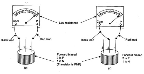
If resistance is shown as in figure (a) is high in one when 3 is +ve and 2 is -ve and low in the other [3 is -ve and 2 is + ve figure (b), then proceed as explained in part II of the Figure. Connect 3 to -ve by red lead and 1 to + ve by black lead as in Figures (c) and (d).

(a) A high resistance would mean 3 and 1 are both n-type and 2 is p-type the base.
(b) A low resistance would mean a forward biasing of 3 and 1 (i.e., 3 is n, 1 is p and 2 is p ). It means the base is 3 and the transistor is p -n-p type.
Identifying the Emitter and Collector leads (Having Known the Base)
In a transistor, the emitter region is heavily doped relative to the collector region. Therefore, the forward resistance of the emitter-base should be lower than that of the collector base. Using an ohm-meter (multimeter set at R) the forward resistance of the lead with the base having a lower value implies that the lead is Emitter and the other offering higher forward with the base is the collector.
(A) When reverse-biased, a diode does not conduct. An LED behaves the same way except that a diode when conducted emits light.
(B) A transistor conducts only when the base-emitter is forward-biased and does not conduct when the base collector is forward-biased.
(C) IC (integrated circuit). Look for the number of legs of the device. Eight or more than eight legs imply that the component is an IC.
(D) Unidirectional flow of current
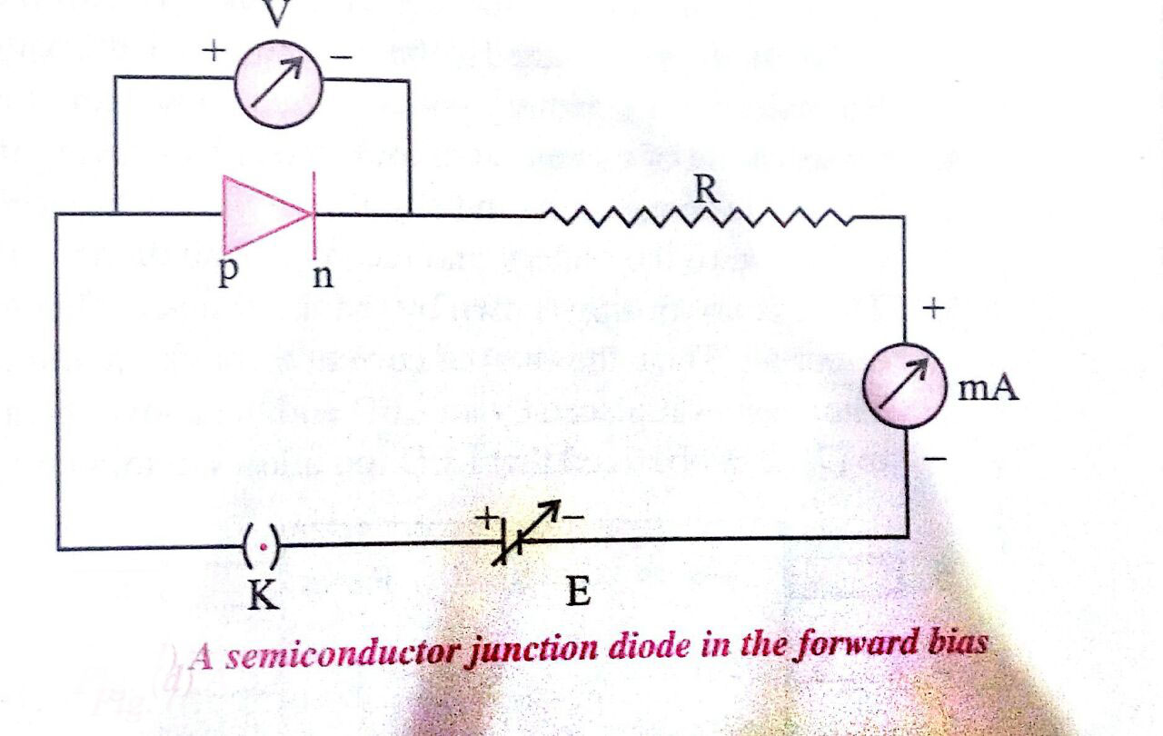
Case of a junction Diode
1. Connect the + ve marked end of the diode to the + ve terminal of a 6 V variable D.C. battery adjusted to minimum voltage.

2. Select the D.C. current at 10 mA range by using the selector switch. Insert one of the metallic ends of a probe in terminal P (+) and the black metallic end into the terminal marked common.
3. Connect the other metalised end of the red probe to the free end of the diode and the metallic end of the black probe into the -ve terminal of the battery eliminator and read the value of current by varying the output of the eliminator. since the diode is forward-biased, it allows the current to pass.
4. Now reverse the terminals of the diode such the end marked-ve is at a higher potential and the one marked + is at a lower potential. Again observe the current in multimeters on the appropriate D.C. milliampere scale. No current reading in the multimeter would indicate that the diode allows the flow of current in one direction only, i.e., the current is unidirectional in a diode.
5. Now replace the diode with the LED and repeat the steps to establish that an LED also allows the flow of current only when it is forward-biased as well as emits light.
(e) Checking whether the diode, a transistor in IC is in working order
1. A diode will conduct only in one direction i.e., first connect the ends of the diode to the two metal ends of the probes and reverse the connecting points. If it conducts in one case, then the diode is in working order. If conducts in both cases or does not conduct in both cases, then it is damaged.
2. Select any two terminals between which there is no conduction in forward or reverse biasing, these will be the emitter and collector if it is not so the transistor is damaged. Now use the third terminal as the base and check whether it conducts with one of the terminals and does not conduct with other terminals showing lower resistance in forward biasing between base-emitter end and higher resistance in forward biasing between base and collector.

3. See the number marked in Fig. (a) and (6) and its specification from the manual.
Check the functioning of various gates e.g., four AND gates on 7408 or four OR gates on 7432(14 terminals on each).
On 7408, two terminals for 0 V and 5 V and 4 gates (AND) each gate with input A, B, and output Y, i.e., 3 terminals or $2+4 \times 3=14$ terminals in all.
Some Solved Examples
Example 1: The base current of the transistor is 105 $\mu_{\mathbf{A}}$ and the collector current is 2.05 mA. Which of the following results is/are correct?
1) $\mathrm{I}_{\mathrm{E}}=2.155 \mathrm{~mA}$
2) $\beta=19.5$
3) $\alpha=0.95$
4) All of the above
Solution:
Use of a multimeter to identify the base of the transistor
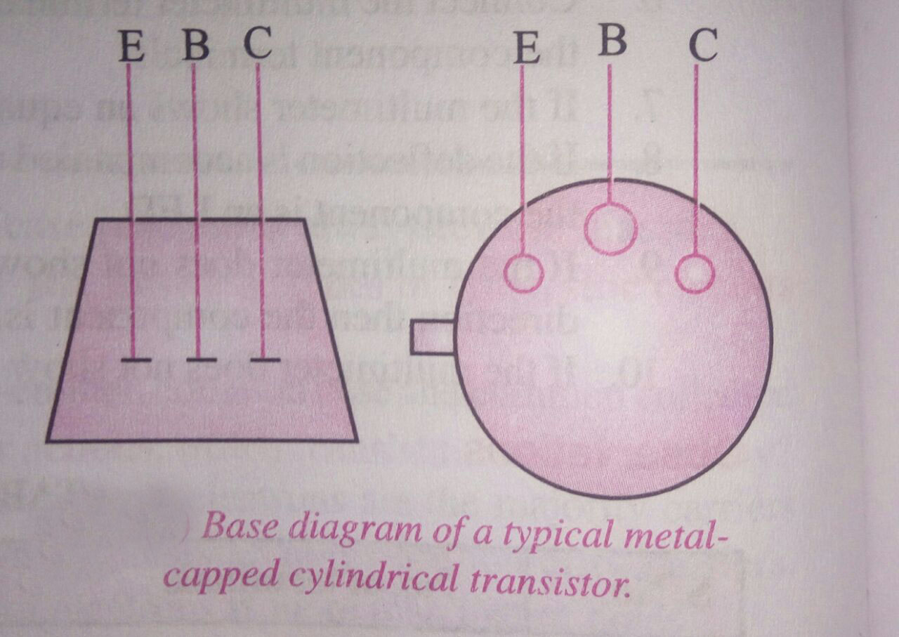
There are three legs which make the three terminals
The collector leg is on the other side and is separated from the other two legs, i.e base and emitter
There is a notch or dot near the collector
The central leg is the base
$\begin{aligned} & I_B=105 \mu \mathrm{A}=0.105 \mathrm{~mA} \\ & I_C=2.05 \mathrm{~mA} \\ & \Rightarrow I_E=I_C+I_B=2.155 \mathrm{~mA} \\ & \beta=\frac{I_C}{I_B}=\frac{2.05}{0.105}=19.5 \\ & \alpha=\frac{I_C}{I_E}=\frac{2.05}{2.155}=0.95\end{aligned}$
Hence the answer is the option (4).
Example 2: A working transistor with its three legs marked P, Q, and R is tested using a multimeter. No conduction is found between P and Q . By connecting the common (negative) terminal of the multimeter to R and the other (positive) terminal to P or Q, some resistance is seen on the multimeter. Which of the following is true for the transistor?
1) It is an NPN transistor with R as a collector.
2)It is an NPN transistor with R as a base.
3)It is a PNP transistor with R as a collector.
4)It is a PNP transistor with R as an emitter.
Solution
Transistor
Three-layered semiconducting device.
NPN or PNP
where
1. Emitter is heavily doped
2. The collector is moderately doped.
3. Base is lightly doped & very thin
It is an NPN transistor with R as a collector.
Since by connecting R to the negative terminal and P or Q to the positive terminal, there is some resistance and hence it is in forward-biased mode.
Hence, R has to be -n type.
R is a collector and the transistor is npn.
Hence the answer is the option (1).
Example 3: An IC (Integrated circuit) is a
1) Single terminal device
2) Two terminal device
3) Three terminal device
4) Multi-terminal device
Solution:
Use of a multimeter to check the electronic component (LED, diode, transistor, IC) is in working order
for the diode to make the connections in forward bias check the current reverse the connections and verify V & I.
For LED also repeat the procedure. Both diode and LED work in forward bias.
wherein
For working on the transistor, we will check if the common terminal and one of the other gives current. If the given current flow in the multimeter is more or less compared to first the transistor is in proper order.
Hence the answer is the option (4).
Summary
To effectively use a multimeter for various electronic components, follow these guidelines. To identify the base of a transistor, set the multimeter to diode mode and test pairs of leads. The base will show a forward voltage drop with one lead and reverse bias with the other. To distinguish between NPN and PNP transistors, note that an NPN transistor will have the base positive relative to the emitter and collector in forward bias, while a PNP transistor will have the base negative. For diodes and LEDs, use the diode test mode to check unidirectional current flow; you should see low resistance in one direction and high resistance in the opposite. LEDs may also light up if the multimeter provides sufficient current. To check other electronic components, measure resistance for resistors, capacitance for capacitors, and continuity or other properties as needed.
