

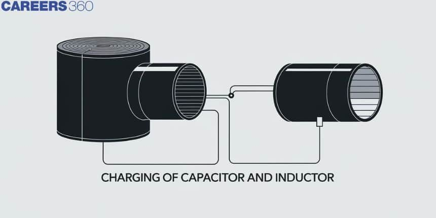
Charging of capacitor and inductor
The charging of capacitors and inductors plays a crucial role in understanding the behaviour of electrical circuits, particularly in energy storage and conversion. A capacitor stores energy in an electric field, while an inductor stores energy in a magnetic field. These components are essential in devices like cameras, where a capacitor helps store energy for the flash, or in power supplies, where inductors smooth out voltage variations. In real life, charging a capacitor is similar to filling a water tank—initially fast, but slowing down as it nears full capacity. Similarly, charging an inductor involves building up a magnetic field gradually, much like winding up a spring. These principles are fundamental to various applications, from smartphones to electric vehicles, showcasing their significance in modern technology.
This Story also Contains
- Charging of a Capacitor
- Discharging of Capacitors
- Charging and Discharging of an Inductor
- Solved Examples Based on Charging of capacitor and inductor
- Summary
Charging of a Capacitor
When a capacitor with zero charges is connected to a battery of emf V through connecting wires, the total resistance including internal resistance of the battery and of the connecting wires is R then after a time t let the charge on the capacitor be q, current be i and $V_c=\frac{q}{C}$,
charge deposited on the positive plate in time $d t$ is so that
$
\begin{aligned}
& d q=i d t \\
& i=\frac{d q}{d t}
\end{aligned}
$
Using Kirchhoffs loop law, $\quad \frac{q}{C}+R i-V=0$
or,
$
R i=E-\frac{q}{C}
$
or, $\quad R \frac{d q}{d t}=\frac{V C-q}{C}$
or, $\quad \int_0^q \frac{d q}{V C-q}=\int_0^t \frac{1}{C R} d t$
or, $\quad-\ln \frac{V C-q}{V C}=\frac{t}{C R}$
or, $\quad 1-\frac{q}{V C}=e^{-t / C R}$
or, $\quad q=V C\left(1-e^{-t / C R}\right)$
Where RC is the time constant $(\tau)$ of the circuit.
At $t=\tau=R C$
$q=C V\left(1-\frac{1}{e}\right)=0.63 C V$
Discharging of Capacitors
If initially a capacitor has a charge Q and is discharged through an external load. Let after a time t the remaining charge in the capacitor be q then
Using Kirchhoff's loop law,
$
\frac{q}{C}-R i=0
$
Here $i=-\frac{d q}{d t}$ because the charge $q$ decreases as time passes.
Thus, $\quad R \frac{d q}{d t}=-\frac{q}{C}$
or, $\quad \frac{d q}{q}=-\frac{1}{C R} d t$
or, $\quad \int_Q^q \frac{d q}{q}=\int_0^t-\frac{1}{C R} d t$
or, $\quad \ln \frac{q}{Q}=-\frac{t}{C R}$
or, $\quad q=Q e^{-t / C R}$

Note: A steady-state capacitor connected to the DC battery acts as an open circuit. The capacitor does not allow a sudden change in voltage.
Charging and Discharging of an Inductor
When an inductor is connected to a DC source of emf v through a resistance R the inductor charges to maximum current $\left(i_0=\frac{V}{R}\right)$ at steady state. If the inductor current is increased from zero at time $=0$ to i at times t then-current i is given by $i=i_0\left(1-e^{\frac{-t}{T}}\right)$ where $\tau=\frac{L}{R}$
$\tau$ is the time constant of the circuit. Here the current is exponentially increasing.
While the discharging of inductor current decreases exponentially and is given by
$
i=i_0\left(e^{\frac{-t}{\tau}}\right)
$

Note: At steady state, an inductor connected to the DC battery acts as a short circuit. The inductor does not allow a sudden change in current.
Recommended Topic Video
Solved Examples Based on Charging of capacitor and inductor
Example 1: Two identical capacitors A and B, charged to the same potential 5 V are connected in two different circuits as shown below at time $\mathrm{t}=0$. If the charge on capacitors A and B at time $\mathrm{t}=\mathrm{CR}$ is $Q_A$ and $Q_B$ respectively, then (Here e is the base of natural logarithm)
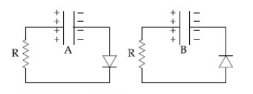
1) $Q_A=V C, Q_B=C V$
2) $Q_A=\frac{C V}{2}, Q_B=\frac{V C}{e}$
3) $Q_A=\frac{V C}{e}, Q_B=\frac{C V}{2}$
4) $Q_A=V C, Q_B=\frac{V C}{e}$
Solution:
Maximum charge on the capacitor $=5 \mathrm{CV}$
(a) is reverse-biased and (b) is forward-biased
(a) (b)
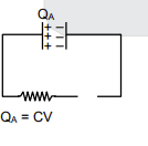
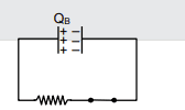
So, $q=q_{\max }\left[e^{-t / R C}\right]$
$
Q_B=\frac{C V}{e}
$
Hence the correct option is (4).
Example 2:

As shown in the figure, a battery of emf $\epsilon$ is connected to an inductor $L$ and resistance $R$ in series. The switch is closed at $t=0$. The total charge that flows from the battery, between $t=0$ and $t=t_c$ ( $\mathrm{t}_{\mathrm{c}}$ is the time constant of the circuit ) is :
1) $\frac{\epsilon L}{R^2}\left(1-\frac{1}{e}\right)$
2) $\frac{\epsilon L}{R^2}$
3) $\frac{\epsilon R}{e L^2}$
4) $\frac{\epsilon L}{e R^2}$
Solution:
As current at any time $t$ is given as
$
\begin{aligned}
& I=I_0\left(1-e^{\frac{-t}{T}}\right)=\frac{\epsilon}{R}\left(1-e^{\frac{-t}{T}}\right) \\
& \text { So } \mathrm{q}=\int_0^{\mathrm{T}_{\mathrm{C}}} \text { idt }
\end{aligned}
$
So integrating this will give a total charge
$
\begin{aligned}
& q=\frac{\varepsilon}{\mathrm{R}}\left[\mathrm{t}-\frac{\mathrm{e}^{-t / \tau}}{\frac{-1}{\tau}}\right]_0^\tau ;=\frac{\varepsilon}{\mathrm{R}}\left[\tau+\tau \mathrm{e}^{-1}-\tau\right] \\
& q=\frac{\varepsilon}{\mathrm{R}} \times \frac{1}{\mathrm{e}} \times \frac{\mathrm{L}}{\mathrm{R}} ; q=\frac{\varepsilon \mathrm{L}}{\mathrm{R}^2 \mathrm{e}}
\end{aligned}
$
Hence the correct option is (4).
Example 3 : The current (i) at time $t=0$ and $t=\infty$ respectively for the given circuit is:

1) $\frac{5 E}{18}, \frac{10 E}{33}$
2) $\frac{10 E}{33}, \frac{5 E}{18}$
3) $\frac{5 E}{18}, \frac{18 E}{33}$
4) $\frac{18 E}{55}, \frac{5 E}{18}$
Solution:
At t = 0, the inductor is open
So the corresponding equivalent circuit is given below

$
\begin{aligned}
& \mathrm{R}_{\mathrm{eq}}=\frac{6 \times 9}{6+9}=\frac{54}{15} \\
& I(\text { at } t=0)=\frac{15 E}{54}=\frac{5 E}{18}
\end{aligned}
$
At $t=\infty_{\text {, }}$ For steady state inductor is replaced by plane wire
So the corresponding equivalent circuit is given below

We can reduce the above circuit to the below circuit.

$\begin{aligned} & \mathrm{R}_{\mathrm{eq}}=\left(\frac{1 \times 4}{1+4}\right)+\left(\frac{5 \times 5}{5+5}\right)=\frac{4}{5}+\frac{5}{2}=\frac{8+25}{10}=\frac{33}{10} \\ & \mathrm{I}=\frac{\mathrm{E}}{\mathrm{R}_{\mathrm{eq}}}=\frac{10 \mathrm{E}}{33}\end{aligned}$
Hence the correct option is (1).
Example 4: Figure shows a circuit that contains four identical resistors with resistance $R=2.0 \Omega$, two identical inductors with inductance $L=2.0 \mathrm{mH}$ and an ideal battery with emf $E=9 \mathrm{~V}$. The current 'i' just after the switch 's' is closed will be :

1) 9 A
2) 2.25 A
3) 3.0 A
4) 3.37 A
Solution:
Just when switch S is closed, the inductor will behave like an infinite resistance. Hence, the circuit will be like

Given: $\mathrm{V}=9 \mathrm{~V}$
From $\mathrm{V}=\mathrm{IR}$
$\mathrm{I}=\mathrm{V} / \mathrm{R}$
Req. $=2+2=4 \Omega$
$\mathrm{i}=9 / 4=2.25 \mathrm{~A}$
Hence the correct option is (2).
Example 5: In the following figure, the charge (in $\mu C$ ) on each condenser in the steady-state will be

1) 12
2) 6
3) 9
4) 3
Solution:
Charging Of Capacitors
$
Q=Q_0\left(1-e^{\frac{-t}{R_c}}\right)
$
wherein
In the R-C circuit (Transient State).
$
i=\frac{10}{(4+1)}=2 \mathrm{amp}
$
.The potential difference across 4 W resistance is $V=2 * 4=8$ volt
In steady-state current flows through 4-ohm resistance only and it is Hence, the potential difference across each capacitor is 4 V
So charge on each capacitor $Q=3 * 4=12 \mu C$
Summary
The charging and discharging of capacitors and inductors follow exponential processes that are essential in various circuits. A capacitor charges by storing energy in an electric field and discharges through a gradual release of this energy, while an inductor stores energy in a magnetic field and behaves similarly in its charging and discharging process. The time constant, denoted as RC for capacitors and L/R for inductors, determines the rate of these processes. These principles are critical in many real-world applications, from power supplies to electronic devices.
