DC Generator - Definition, Parts, EMF Equation, Applications, FAQs
A direct-current (DC) generator is a rotating machine that creates a voltage and current output that is unidirectional. The essential operating principles are the same as for synchronous generators. The rate of change of the magnetic field across the coils as the machine rotates induces voltage in the coils. Because the coil flux increases and subsequently declines with a zero average value, the induced voltage is naturally alternating.

Electrical generators are self-contained units that provide power when the local grid fails. During power outages, these DC generators provide backup power to homes and businesses. DC Generators do not produce the electricity; instead, they convert the mechanical or the chemical energy into it. Generators are divided into two categories based on their output: AC and DC. We'll go through DC generators in great detail in this essay.
Prior to the availability of inexpensive rectifier systems supplied by alternators, direct-current generators were widely used. They were commonly used for charging batteries and electrolytic systems, for example. The direct-current generator has an advantage over the alternator-rectifier in some situations because it can also function as a motor, reversing the direction of power flow. To achieve power reversal, an alternator, on the other hand, requires a more complex rectifier-inverter system.
Also read -
What is Direct-Current Generator?
A DC generator is a type of electrical machine that converts mechanical energy to electricity. An emf is created when a conductor slashes magnetic flux, according to Faraday's Laws' of electromagnetic induction. When the conductor circuit is closed, this electromotive force can generate a current flow.
Parts of a DC Generator
A DC generator can function as a DC motor without requiring any modifications to its design. As a result, a DC machine can be defined as a DC motor or a DC generator. The fundamental components of a DC Generator are outlined below.
- Stator: - The stator's primary role is to create magnetic fields in which the coil may spin. A stator is made up of two magnets with opposite polarity facing each other. These magnets are positioned to fit within the rotor's area.
- Rotor: - A DC machine's rotor is made up of slotted iron laminations that are layered to form a cylindrical armature core. The lamination's purpose is to reduce the loss caused by eddy current.
- Armature Windings: - Armature windings are connected in series to parallel in a closed circuit to increase the sum of produced current.
- Poles: - A pole's job is to keep the field windings in place. These windings are wound on poles and the armature windings connect them in series or parallel.
- Pole Shoe: - The pole shoe is used to disperse the magnetic flux and keep the field coil from falling.
- Yoke: - Yoke is the name given to the DC generator's exterior construction. It's made of either cast iron or steel and provides the mechanical power needed to transport the magnetic flux created by the poles.
- Commutator: - Within the armature winding, a commutator acts as a rectifier, converting AC electricity to DC voltage. It has a copper segment, with mica sheets protecting each copper segment from the others and is situated on the machine's shaft.
- Brushes: - Brushes can be used to ensure electrical connections between the commutator and the external load circuit.
Related Topics Link, |
How Does DC Generator Work?
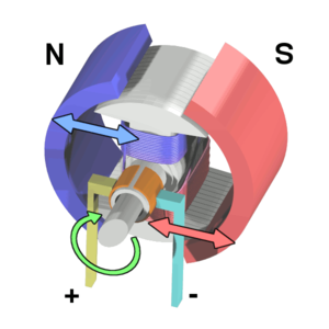
When a current-carrying conductor is put in a fluctuating magnetic field, an emf is induced in the conductor, according to Faraday's law of electromagnetic induction. The direction of the induced current changes as the direction of motion of the conductor changes, according to Fleming's right-hand rule. Consider an armature revolving clockwise and a conductor travelling upwards from the left. The direction of the conductor's travel will be reversed downward after the armature completes a half rotation. As a result, the current in each armature will alternate in direction. However, when a current reversal occurs in a split ring commutator, the armature conductor connections are reversed. As a result, the terminals have a single-direction current.
DC Generator Diagram

E.M.F DC generator equation
NCERT Physics Notes :
The DC generator's emf equation is given by the equation:

Where,
- The total number of armature conductors is denoted by Z.
- The number of poles in a generator is denoted by P.
- The number of parallel lanes within the armature is denoted by A.
- The rotation of the armature in r.p.m. is denoted by N.
- E is the induced e.m.f. in any parallel armature channel.
- The generated e.m.f in any of the parallel lanes is Eg.
- The number of turns per second is N/60.
- One turn will take dt = 60/N seconds.
Also read :
- NCERT solutions for Class 12 Physics Chapter 6 Electromagnetic Induction
- NCERT Exemplar Class 12 Physics Solutions Chapter 6 Electromagnetic Induction
- NCERT notes Class 12 Physics Chapter 6 Electromagnetic Induction
DC Generator Losses
The input power is not totally translated into the output power in a DC machine. A portion of the supplied power is squandered in various ways. The losses in a DC machine are divided into four categories:
- Copper Loss: - Copper loss occurs as current passes through the winding. The resistance in the winding causes these losses. The armature loss, field winding loss, and brush contact resistance loss are the three types of copper loss.
- Core Losses or Iron Losses: - As the armature rotates in the magnetic field, some losses in the iron core occur. These are referred to as core losses. Hysteresis and Eddy current losses are the two types of losses that occur.
- Mechanical Losses: - Mechanical losses are losses that emerge as a consequence of friction between the generator's parts.
DC Generator Applications
- Using field regulators, an independently excited type DC generator is employed for power and lighting.
- Arc lamps use a series DC generator for a reliable current generator, illuminating, and booster.
- Compound at a reasonable level Hostels, offices, and lodges rely on DC generators for power.
- Power for DC welding machines is provided by compound DC generators.
- To compensate for the voltage loss in the feeders, a DC generator is required.
Also check-
Frequently Asked Questions (FAQs)
A voltage is generated in the coils of the armature as it rotates. The rotational emf of a generator is known as the Generated emf or Armature emf and is indicated by Er = Eg. The rotational emf of a motor is known as Back emf or Counter emf and is written as Er = Eb.
The magnetic field system, armature and commutator, and brush gear are the three primary components. Magnetic frame and yoke, pole core and pole shoes, field or exciting coils, armature core and windings, brushes, end housings, bearings, and shafts are the other components of a DC Generator.
Faraday's rules of electromagnetic induction determine how a DC generator works. When a conductor is placed in a fluctuating magnetic field (or when a conductor is moved in a magnetic field), an EMF is induced in the conductor, according to Faraday's law.
DC generators, like other machines, have various drawbacks, such as the fact that they cannot be used to power a transformer. Copper losses, eddy current losses, hysteresis losses, and mechanical losses all contribute to the low efficiency of DC generators. There would be a voltage decrease over vast distances.
DC Generators Uses: Batteries are charged, lights are turned on, and alternators are excited by these generators. Field excitation current is used in DC locomotives to provide regenerative braking. When speed control is required in DC motors, they are utilised.