

How Diodes Work As a Rectifier - Half Wave Rectifier & Full Wave Rectifier
A rectifier will turn an AC power source into a DC power source and is due to the diode. Rectifiers can be classified as half wave and full wave rectifiers. The ripple factor of the half wave rectifier can be calculated as the ratio of the rms value of the AC circuit to the rms value of the DC circuit. A crystal diode may be used as the rectifier. In this article, we will study in detail what is rectification, what is half wave rectifier and full wave rectifier, advantages of half wave rectifier, disadvantages of half wave rectifier, form factor of half wave rectifier, ripple factor of half wave rectifier, advantages of full wave rectifier, disadvantages of full wave rectifier, form factor of full wave rectifier, ripple factor of full wave rectifier, half wave rectifier diagram, full wave rectifier diagram and efficiency of half wave and full wave rectifiers.
This Story also Contains
- What is Diode?
- What is Half Wave Rectifier
- Characteristics Of Half Wave Rectifier
- Advantages of Half Wave Rectifier
- Disadvantages of Half Wave Rectifier
- What is Full Wave Rectifier
- Characteristics Of Full Wave Rectifier
- Advantages of Full Wave Rectifiers
- Disadvantages of Full Wave Rectifier
What is Diode?
A diode comes in different shapes and sizes. They normally have a black cylinder-shaped body as a band at one end as well as some leads coming out to permit us to connect it into a circuit. One end is known as the anode and the other end is known as the cathode. A diode allows the current to flow in only one direction in a circuit from anode to cathode. Let us imagine a water pipe or the swing valve installed, as water flows through the pipe it will push the swing gate open and continue to flow through it. However, if the water changes direction the water will thrust the gate shut and it will stop it from flowing. Thus water will only flow in individual directions. This is very similar to the use of diodes in a circuit, we practice them to regulate the direction of current in a circuit.
If we join a diode into a simple LED, we see that the LED will individually turn on when the diode is connected correctly and that's because it allows current to flow in one direction. So depending upon which way the diode is installed, the circuit will act as either a conductor or an insulator. For the diode to act as a conductor, the stripe end is connected to the negative, and the black end is connected to the positive. This allows the electric current to flow, we call it forward bias. If we interchange the diode, it will turn into an insulator and the current will not flow. We call this the reverse bias. We use copper wires as a conductor since copper has a lot of free electrons which makes it easier to pass electricity through We use rubber to insulate the copper wires and keep us safe because rubber is an insulator which means its electrons are held very closely and they can't move amongst atoms. Now let us understand how half wave rectifier and full wave rectifiers work, rectifier efficiency, and the types of rectifiers (i.e. half wave rectifiers and full wave rectifiers)
What is Half Wave Rectifier
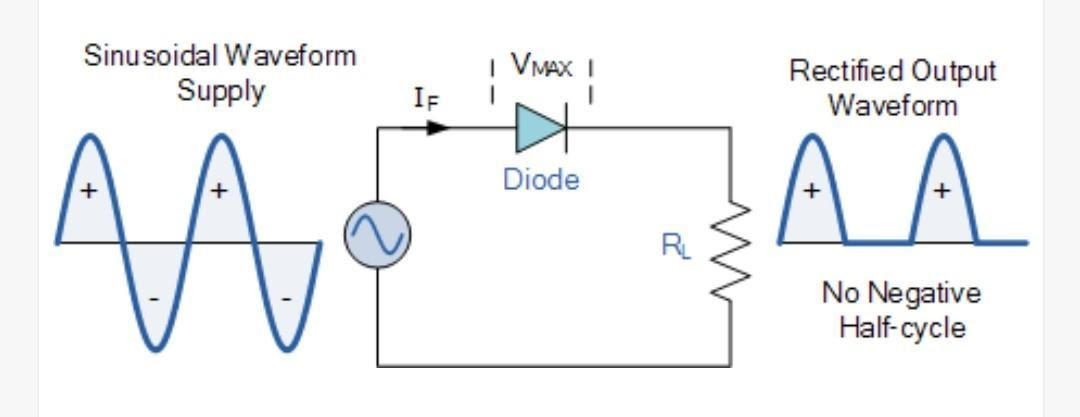
In a wave rectifier AC power supply is connected to a single diode. So how many diodes are used in a half-wave rectifier? The answer is one diode. In a half-wave rectifier, the supply of AC power source is connected to the resistive load through a single diode. So in the positive half cycle is forward bias which means the diode is conducting. So since the diode is conducting we get an output for the first positive half cycle. Now during the negative half cycle, the diode is reverse bias. So in that case the diode will not conduct. Since there is practically no current flowing. We say that the diode is nonconducting and we get a zero output. Again during the next positive half cycle, the diode is conducting so we have output. During the next negative half cycle once again it will be in reverse bias and we have zero output. So the output is only in one direction. It is only in a positive direction and there is no negative half-cycle present. The output is now said to be rectified because it is only flowing in one direction. As only a positive half cycle of the input wave is used it is known as a half-wave rectifier. Let us study the average and rms value of the half-wave rectifier.
Characteristics Of Half Wave Rectifier
- The average value of half wave rectified sine wave is given as:
$$
V(s)=V_m \sin (\omega t)
$$
where $V_m$ is the maximum value of the supply voltage.
$$
V_m=\sqrt{2} V_{\mathrm{rms}}
$$
where $V_{\mathrm{rms}}$ is the RMS value of the supply voltage.
$$
V_{\mathrm{dc}}=\frac{V_m}{\pi}=0.318 V_m
$$
where $V_{\mathrm{dc}}$ is the average DC voltage across the load.
- Average DC through load
$I_dc$=average DC through load
$I_dc$=0.318 $I_m$
Where $I_m$ = max. Value of current
-
Now, the form factor is the ratio of the RMS value to the average value of the output power
$F=RMS$ value average value
The form factor of half-wave rectified sine wave is equal to 1.57.
-
Next is PIV (PIV full form is picking inverse voltage of the half-wave rectifier), the maximum voltage across the diode in the reverse direction. Which is equal to V(m)
-
The ripple factor of the half-wave rectification is $1.21$
Ripple factor formula,
$\gamma=\sqrt{\left(\frac{V_{\text {max }}}{V_{D C}}\right)^2-1}$
-
The rectification efficiency of a half-wave rectifier is the ratio of output power to the input power. The maximum efficiency of a half-wave rectifier is equal to 40.6%.
Advantages of Half Wave Rectifier
- Simple circuit
- Cost small
- Easy to practice
- Simple structure.
Disadvantages of Half Wave Rectifier
- Utility factor is low
- Output voltage is low
- High power loss.
What is Full Wave Rectifier
In the full wave rectifier, the AC power source is connected to load resistance through a transformer and two diodes. How many diodes are used in a full-wave rectifier? The answer is two diodes So full wave rectifier circuit using two diodes and the center transformer is shown in the figure below.
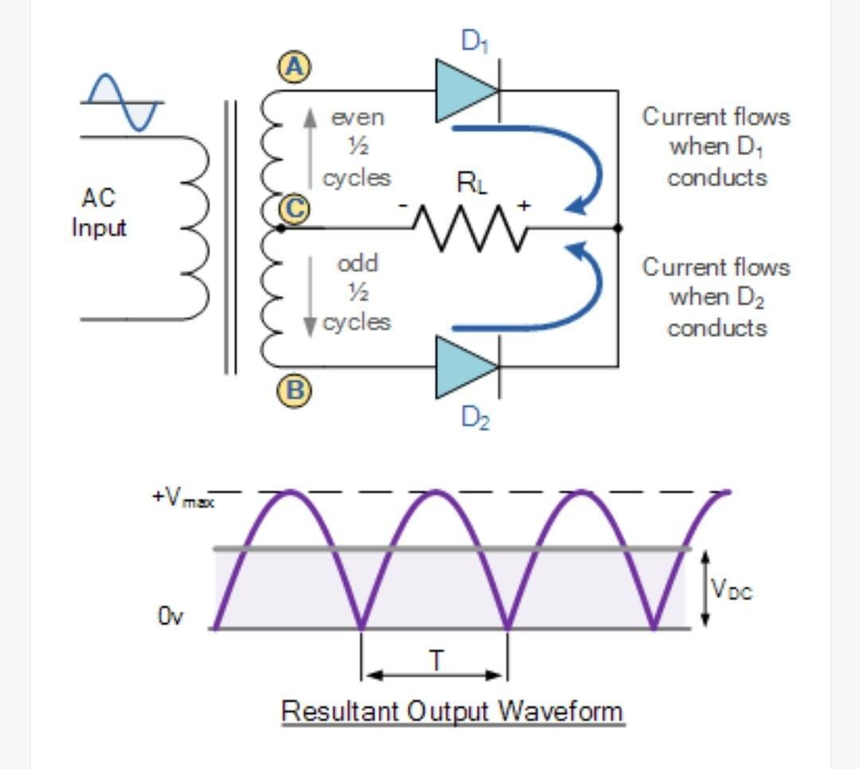
Both half cycles of the input are utilized with the help of two diodes working alternatively. The use of a transformer is essential. In the half cycle, the input current is transferred to the output current with the help of the transformer. The output current flows through the diode $D_1$ and $R_L$ resistive load in a clockwise direction. So in the positive half cycle, the output voltage that appears across $R_L$ is equal to the input voltage of the half cycle. In the negative half cycle, the output current flows through diode $D_2$ and resistive load $R_L$ in an anticlockwise direction. So the output voltage across $R_L$ is the input voltage of the negative half cycle but with opposite polarity. So current flowing through $R_L$ is in the same direction which is why the output voltage across $R_L$ is in the positive direction only. Let us study the average and rms value of the full wave rectifier.
Characteristics Of Full Wave Rectifier
-
The input signal is the sinusoidal source and is given as:
$$
V(s)=V_m \sin (\omega t)
$$
Where $V_m=$ max. value of supply voltage.$$
V_m=\sqrt{2} V
$$
Where $V=\mathrm{rms}$ value of supply voltage.
$V_{\mathrm{dc}}=$ average DC voltage across the load$$
V_{\mathrm{dc}}=\frac{2 V_m}{\pi}=0.636 V_m
$$
Average DC through load:$$
\begin{aligned}
& I_{\mathrm{dc}}=\text { average } \mathrm{DC} \text { through load } \\
& I_{\mathrm{dc}}=0.636 I_m
\end{aligned}
$$
Where $I_m=$ max. value of current. - Ripple factor of the full wave rectifier
$F=RMS$ value average value
Which is equal to $1.11$
-
Next is the PIV of the diode (PIV full form is the pick inverse voltage of the half-wave rectifier), the maximum voltage across the diode in the reverse direction. Which is equal to 2V(m).
-
The ripple factor for the full wave rectifier is equal to $0.482$
Ripple factor formula,
$$\gamma=\frac{V_{\mathrm{RMS}}}{V_{\mathrm{DC}}}$$
-
The rectification efficiency of a full wave rectifier is the ratio of output power to input power. The rectification efficiency of full wave rectifier is equal to $81.2%$.
Advantages of Full Wave Rectifiers
- High efficiency
- Low ripple factor
- Large output voltage.
Disadvantages of Full Wave Rectifier
- Need two diodes
- Costlier and not suitable
- Requires more components
Also read:
Frequently Asked Questions (FAQs)
Yes, a full wave rectifier is better.
PIV is peak inverse voltage.
The ripple factor formula can be written as
F=RMS valueaverage value
40.6%
81.2%
