

LCR Circuit - Phasor Diagram, FAQs
The series LCR circuit is one of the most important topics in Class 12 Physics and competitive exams like JEE Main and NEET. An LCR circuit contains a resistor (R), inductor (L), and capacitor (C) connected in series to an AC source.
In this article, you will learn the definition of an LCR circuit, the phasor diagram, the impedance formula, and the condition for resonance. You will also understand the Q-factor, reactance, and the working of a series LCR circuit in a simple, easy-to-remember way.
This Story also Contains
- What is LCR circuit?
- Phasor Diagram of a Series LCR Circuit
- Impedance of Series LCR Circuit
- Phase Difference $\mathbf{(} \mathbf{\Phi}$ ) Between Voltage and Current
- Resonance in Series LCR Circuit
- Power Consumed in a Series LCR Circuit
- Power Factor
- Characteristics of Series Resonance
- Quality Factor (Q Factor)
- Uses of LCR Circuit
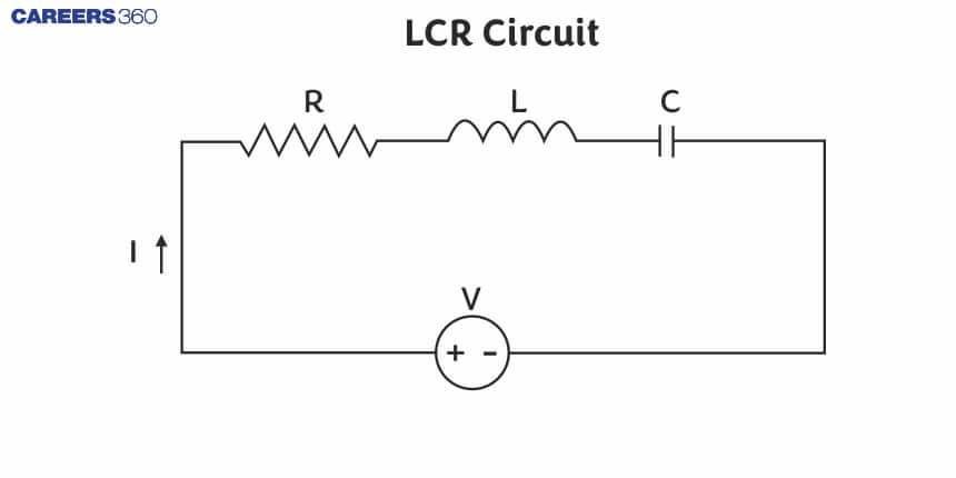
What is LCR circuit?
An LCR circuit (also called an RLC circuit) is an electrical circuit that consists of:
- R - Resistor
- L - Inductor
- C-Capacitor
connected in series to an AC voltage source.
The applied alternating emf is:
$
\varepsilon=\varepsilon_0 \sin (\omega t)
$
Since the components are connected in series, the same current flows through R, L, and C.
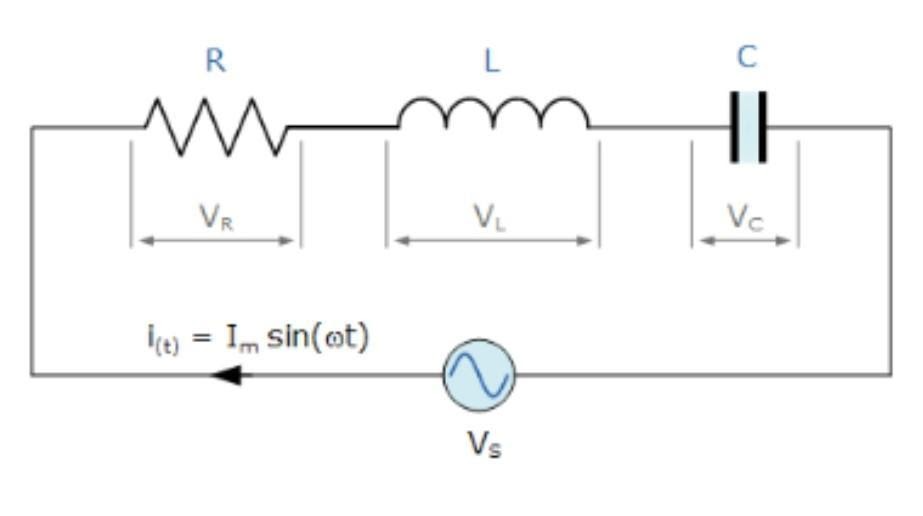
1. Voltage across Resistor (VR)
$
V_R=I R
$
- In phase with current
- Phasor is along the direction of current
2. Voltage across Inductor (VL)
$
V_L=I X_L=I \omega L
$
- Leads current by $90^{\circ}$
- Phasor is drawn $\mathbf{9 0}^{\boldsymbol{\circ}}$ anticlockwise from current
3. Voltage across Capacitor (VC)
$
V_C=I X_C=I\left(\frac{1}{\omega C}\right)
$
- Lags current by $90^{\circ}$
- Phasor is drawn $\mathbf{9 0}^{\boldsymbol{\circ}}$ clockwise from current
Also read :
Phasor Diagram of a Series LCR Circuit
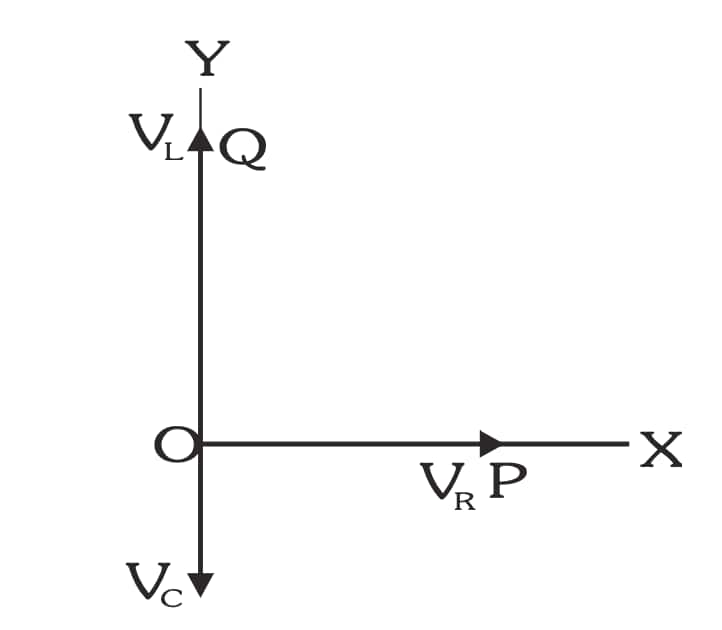
- $V_R$ is horizontal
- $V_L$ is drawn upward
- $V_C$ is drawn downward
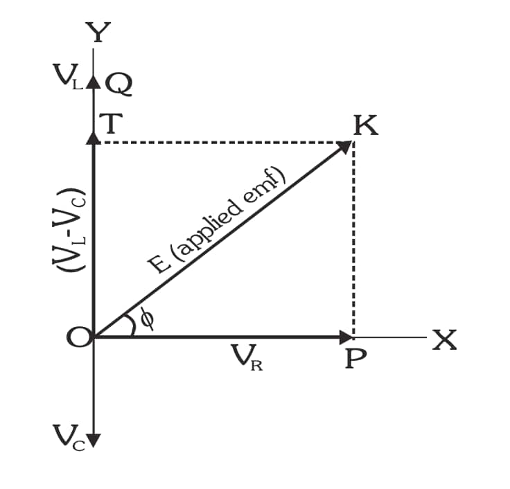
- $V_L-V_C$ gives the net reactive voltage
The diagonal of the phasor diagram gives the applied voltage $\varepsilon_0$.
Impedance of Series LCR Circuit
Using Pythagoras rule from the phasor diagram:
$
Z=\sqrt{R^2+\left(X_L-X_C\right)^2}
$
where
$
X_L=\omega L, \quad X_C=\frac{1}{\omega C}
$
Current in the circuit becomes:
$
I_0=\frac{\varepsilon_0}{Z}
$
Phase Difference $\mathbf{(} \mathbf{\Phi}$ ) Between Voltage and Current
$
\tan \phi=\frac{X_L-X_C}{R}
$
- If $X_L>X_C \rightarrow$ Inductive circuit
- If $X_L<X_C \rightarrow$ Capacitive circuit
- If $X_L=X_C \rightarrow$ Purely resistive circuit ( $\phi=0$ )
Also read -
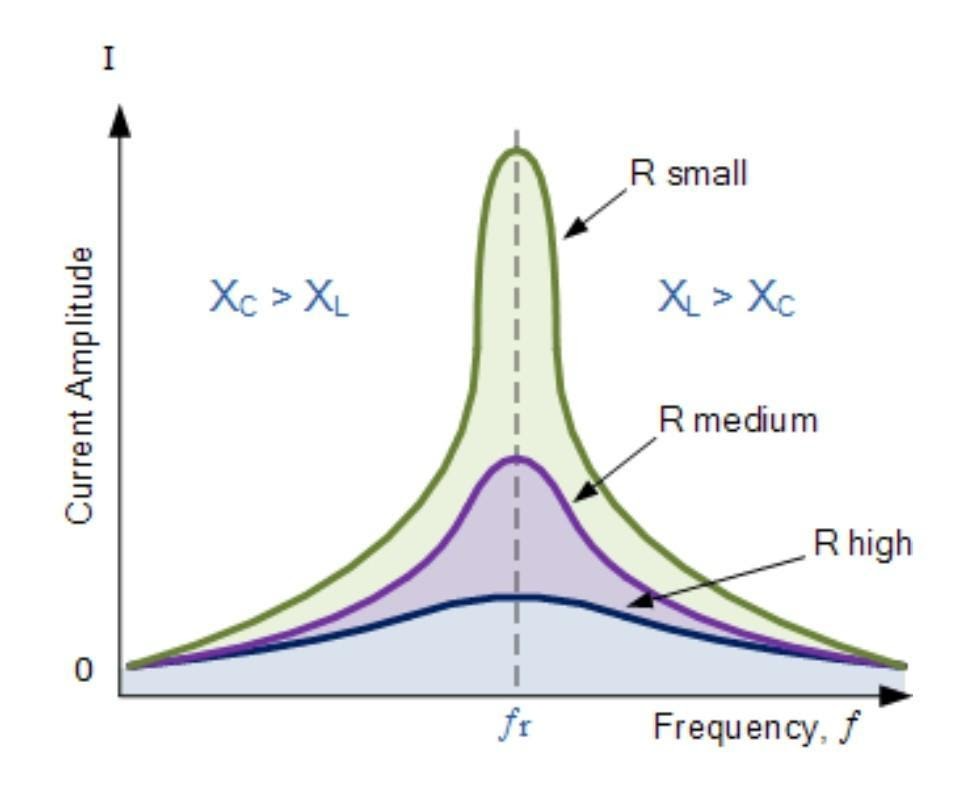
Resonance in Series LCR Circuit
A series LCR circuit is in resonance when:
$
X_L=X_C
$
This gives:
$
\omega_0=\frac{1}{\sqrt{L C}}
$
Resonant frequency:
$
f_0=\frac{1}{2 \pi \sqrt{L C}}
$
At Resonance:
- $Z=R$ (minimum impedance)
- $I=I_{\text {max }}=\frac{\varepsilon_0}{R}$
- Voltage and current are in phase
- Circuit behaves like a pure resistor
- Power factor $=1$
Application: Radio tuning circuits, filters, wireless communication.
Power Consumed in a Series LCR Circuit
Let the applied alternating voltage be:
$
v=V_0 \sin \omega t
$
The resulting current in the circuit is:
$
i=I_0 \sin (\omega t-\phi)
$
where $\phi$ is the phase difference between voltage and current.
The instantaneous power supplied to the circuit is:
$
\begin{gathered}
p=v \cdot i \\
p=V_0 \sin \omega t \cdot I_0 \sin (\omega t-\phi)
\end{gathered}
$
Using the trigonometric identity:
$
\sin A \sin B=\frac{1}{2}[\cos (A-B)-\cos (A+B)]
$
we get:
$
p=\frac{V_0 I_0}{2}[\cos \phi-\cos (2 \omega t-\phi)]
$
The average value of $\cos (2 \omega t-\phi)$ over one complete cycle is zero.
Hence, the average power consumed in the circuit is:
$
P=\frac{V_0 I_0}{2} \cos \phi
$
$\begin{aligned} V_{r m s} & =\frac{V_0}{\sqrt{2}}, \quad I_{r m s}=\frac{I_0}{\sqrt{2}} \\ P & =V_{r m s} I_{r m s} \cos \phi\end{aligned}$
Power Factor
The quantity $\cos \phi$ is called the power factor of the circuit.
For a series LCR circuit:
$
\cos \phi=\frac{R}{Z}
$
where the impedance $Z$ is given by:
$
Z=\sqrt{R^2+\left(X_L-X_C\right)^2}
$
Thus, the average power can also be written as:
$
P=I_{r m s}^2 R
$
Characteristics of Series Resonance
1. Occurs when $X_L=X_C$.
2. Impedance is minimum (equal to R ).
3. Current is maximum.
4. Voltage across $L$ and $C$ are equal and opposite.
5. Power dissipation is maximum.
6. Power factor $=1$.
NCERT Physics Notes:
Quality Factor (Q Factor)
The Q-factor shows how sharp the resonance is.
$
Q=\frac{\omega_0 L}{R}=\frac{1}{\omega_0 C R}
$
Also:
$
Q=\frac{f_0}{\Delta f}
$
- High Q → sharper resonance (good selectivity)
- Low Q → broad resonance
Bandwidth of LCR Circuit
$
\Delta f=f_2-f_1=\frac{f_0}{Q}
$
where $f_1$ and $f_2$ are frequencies at which current drops to $I_{\max } / \sqrt{2}$ (half-power frequencies).
Uses of LCR Circuit
- Radio receivers
- Tuned circuits
- Signal processing
- Filtering specific frequencies
- Wireless transmitters
- Sensors and oscillators
Also check-
Frequently Asked Questions (FAQs)
When the period of applied frequency matches with the natural frequency of a body, the amplitude of vibration becomes maximum. This phenomenon is called resonance.
Forced vibrations are the vibrations in which a body vibrates with a frequency other than its natural frequency under the influence of an external force.
This is since the impedance of the circuit is at its lowest so easily accepts the current whose frequency is equivalent to its resonant frequency.
For high frequency A.C in radio communications, a series resonance circuit is used. LCR circuits are utilized in frequency filter circuits like in high pass filter, low pass filter and band pass filter.
A circuit is supposed to be in resonance when the applied voltage and current are in phase.
In a series LCR circuit, the length of a phasor represents the magnitude of voltage or current.
An LCR circuit is important because:
It produces resonance, giving maximum current.
It is used in radio tuning and communication systems.
It helps in signal filtering (selecting one frequency and rejecting others).
It improves power factor in AC circuits.
It is used in oscillators, sensors, audio devices, and power electronics.
