

AC Voltage Across LCR
An LCR circuit is known as a tuned circuit or a resonant circuit. It is an electrical circuit which consists of an inductor, capacitor and resistor connected in series or parallel. The full form of an LCR circuit is an inductance-capacitance-resistance circuit and this type of circuit plays an important role in tuning purposes. The series LCR circuit is mostly used to provide voltage magnification.
This Story also Contains
- Importance Of LCR Circuit
- Analysis Of Series LCR Circuit
- Parallel LCR Circuit
- Application Of LCR Circuit
Importance Of LCR Circuit
Capacitive reactance, Inductive reactance and electrical reactance are three significant reactance which creates a series LCR circuit. With the help of LCR circuits, we can reduce power consumption by controlling the current flowing through various electronic devices. By using these circuits, we can save our electronic appliances from overheating by controlling the current flow.
Analysis Of Series LCR Circuit
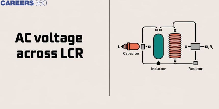
A circuit which contains pure resistance connected in series with a pure capacitor of capacitance and pure inductor of inductance is called an LCR circuit. A sinusoidal voltage is applied and current flows through the circuit. An alternating current or AC generator is generally used as an AC voltage source in the LCR circuit.
Series LCR circuit is shown in the figure given below. Here, the total voltage across the series LCR Circuit is V=V_{m}sin\omega t ![]()
This is a series LCR circuit so the current remains the same through all the components but the voltage across all the components would be different. So, the voltage across the three components can be written as,
V_{R}=IR
![1707721151997]() which is the voltage across the resistance R
which is the voltage across the resistance RV_{L}=IX_{L}
![1707721151759]() which is the voltage across the inductor L
which is the voltage across the inductor LV_{C}=IX_{C}
![1707721152107]() is the voltage across the capacitor C
is the voltage across the capacitor C
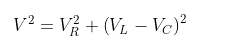
We can write,
V^{2}=V_{R}^{2}+\left ( V_{L}-V_{C} \right )^{2}
V=\sqrt{\left ( IR \right )^{2}+\left ( IX_{L}-IX_{C} \right )^{2}}
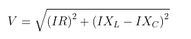
So, V=I\sqrt{R^{2}+\left ( X_{L}-X_{C} \right )^{2}}

The above equation can be written as V=IZ ![]()
Where, Z=\sqrt{R^{2}+\left ( X_{L}-X_{C} \right )^{2}}
![]()
Where Z is the impedance and X_{L} ![]() and X_{C}
and X_{C} ![]() is the impedance of the inductor and impedance of the capacitor respectively.
is the impedance of the inductor and impedance of the capacitor respectively.
LCR series circuits are used in signal processing and radio communications for choosing a specific band of frequencies.
The resultant voltage will depend upon the impedance of the inductor and the impedance of the capacitor. So, we get three cases as follows:
When the impedance of the inductor is more than the impedance of the capacitor: In this case, the inductive effect will be more So, the circuit will act as an RL series circuit. In a purely inductive circuit, voltage leads the current by 90 degrees.
When the impedance of the capacitor is more than the impedance of the inductor: In this case, the capacitive effect will be more. So, the circuit will act as an RC series circuit. In a purely capacitive circuit, current leads the voltage by 90 degrees.
When the impedance of the inductor is equal to the impedance of the capacitor: In this case, both the values are equal. So, the circuit will act as a purely resistive circuit. In this type of circuit, the voltage would be in phase with the current.
Parallel LCR Circuit
In this type of circuit, the inductor, capacitor and resistor all are connected in parallel across a voltage supply. In the parallel LCR circuit, the voltage remains the same across its three components but the supply of current gets divided. Parallel LCR circuit is used in induction heating systems and for tuning purposes also. This type of circuit is also used as a filter circuit and as a current amplifier.
Application Of LCR Circuit
LCR circuit is used in automobile ignition to generate high voltage and is also used in the filtration of water in water purifiers.
LCR circuit is used in oscillator circuits.
It is useful in power transformers to avoid sudden faults in the currents.
It is used in CFL(Compact fluorescent lamps) bulbs to improve the operating power factor of the lamp to reduce electricity consumption and it can also be used in the tuning of radio or audio receivers.
Frequently Asked Questions (FAQs)
Resistance is the opposition to the flow of current. Resistance can be used for both AC and DC circuits. It has real value.
Reactance is the opposition to change in the current. It is valid only for AC circuits. It has always had imaginary values.
Reactance is the opposition offered to AC by circuit components (inductor and capacitor).
It is an arrangement of two conductors separated by an insulating medium which is used to store electric charge and electrical energy.
In series LCR circuits, when the frequency is increased, the inductive reactance increases and capacitive reactance decreases.
The inductor is a passive component which can be used in most electronic circuits to store energy in the form of magnetic energy when electricity is applied to it. There are four different types of inductors:
Iron Core Inductor
Iron Powder Inductor
Air Core Inductor
Ferrite Core Inductor
