AC Voltage Applied To A Capacitor

AC Voltage Applied To A Capacitor

Edited By Vishal kumar | Updated on Jul 02, 2025 05:58 PM IST

When an AC voltage is applied to a capacitor, the alternating current creates a constantly changing electric field within the capacitor, causing it to charge and discharge periodically. This behaviour results in a phase difference between the voltage and current, with the current leading the voltage by 90 degrees. Understanding this interaction is fundamental in AC circuit analysis and is widely applied in various technologies. In real life, capacitors are crucial in power supplies for smoothing voltage fluctuations, tuning radios and television circuits for frequency selection, and developing filters for audio and communication systems. This article explores the principles and practical implications of applying AC voltage to a capacitor.

This Story also Contains
  1. AC Voltage Applied to a Capacitor
  2. Solved Examples Based on AC Voltage Applied to a Capacitor
  3. Hence, the answer is the option (1).
  4. Summary
AC Voltage Applied To A Capacitor

AC Voltage Applied to a Capacitor

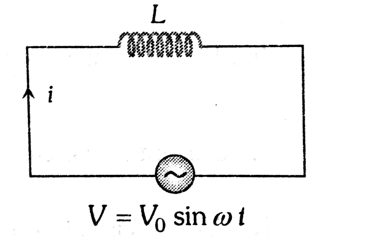
When an AC voltage is applied to a capacitor, the capacitor undergoes a continuous cycle of charging and discharging, responding to the alternating current's oscillations. This results in a phase difference where the current leads the voltage by 90 degrees, a distinctive characteristic in AC circuits. The circuit containing alternating voltage source $V=V_0 \sin \omega t$ is connected to a capacitor of capacitance C.

Suppose at any time t, q is the charge on the capacitor and i is the current in the circuit. Since there is no resistance in the circuit, the instantaneous potential drop $q / C$ across the capacitor must be equal to the applied alternating voltage,

$\frac{q}{C}=V_0 \sin \omega t$

Since $i=d q / d t$ is the instantaneous current in the circuit so,

$\begin{aligned} i= & \frac{d q}{d t}=\frac{d}{d t}\left(C V_0 \sin \omega t\right) \\ & =C V_0 \omega \cos \omega t \\ & =\frac{V_0}{(1 / \omega C)} \cos \omega t \\ & =i_0 \cos \omega t=i_0 \sin \left(\omega t+\frac{\pi}{2}\right)\end{aligned}$

Where, $i_0=\frac{V_0}{(1 / \omega C)}$ is the peak value of current.

Comparing the equation of current with $V=V_0 \sin \omega t$ , we see that in a perfect capacitor current leads the emf by a phase angle of $\pi / 2$.

Again comparing the peak value of current with Ohm's law, we find that quantity 1/ωC has the dimension of the resistance.

Thus the quantity $X_C=\frac{1}{\omega C}=\frac{1}{2 \pi f C}$ is known as capacitive reactance.

Phase difference (between voltage and current):

$\phi=-\frac{\pi}{2}$

Power

P= 0

Power factor

$\cos (\phi)=0$

Time difference

T.D = $\frac{T}{4}$

Recommended Topic Video

Solved Examples Based on AC Voltage Applied to a Capacitor

Example 1: A circuit has a resistance of 12 ohms and an impedance of 15 ohms. The power factor of the circuit will be

1) 0.8

2) 0.125

3) 1.25

4) 0.4

Solution:

R.L Circuit Voltage

$\begin{aligned} & V_R=I R \\ & V_L=I X_L\end{aligned}$

wherein

Power factor

$\cos \phi=\frac{R}{\sqrt{R^2+X_c^2}}$

Solution is correct

Capacitive current (C) Current

$i^{\prime}=i_0^{\prime} \sin \left(\omega t+\frac{\pi}{2}\right)$

wherein

Inductive circuit (L) Current

$i^{\prime}=i_0^{\prime} \sin \left(\omega t-\frac{\pi}{2}\right)$

wherein

Power factor $\cos \phi=\frac{R}{Z}=\frac{12}{15}=0.8$

Hence, the answer is the option (1).

Example 2:

Find peak current (in amperes) is given circuit

1) 0.628

2) 1.34

3) 0.444

4) 0.222

Solution:

Peak Current

$\begin{aligned} & i_0^{\prime}=\frac{v_0}{X_C}=V_0 \omega C=V_0(2 \pi \nu C) \\ & V_{r m s}=\frac{V_o}{\sqrt{2}} \\ & V_o=\sqrt{2} \times V_{r m s} \\ & V_o=\sqrt{2} \times \frac{200}{\sqrt{2}} \\ & V_{\mathrm{o}}=200 \mathrm{mV}\end{aligned}$

Now, peak current,
$
P_o=\frac{V_o}{X_C}
$
$
\begin{aligned}
& i_o=V_o W C=V_o \times 2 \pi f c \\
& i_o=200 \times 2 \times \pi \times 50 \times 10 \times 10^{-3} \\
& i_o=200 \pi \\
& i_o=0.628 \mathrm{~A}
\end{aligned}
$

Hence, the answer is the option (1).

Example 3: Calculate the reactance in the given circuit

1) $\pi$
2) $\frac{2}{\pi}$
3) $2 \pi$
4) $\frac{1}{\pi}$

Solution:

Peak Current

$
i_0^{\prime}=\frac{v_0}{X_C}=V_0 \omega C=V_0(2 \pi \nu C)
$

Capacitive resistance is,
$
\begin{aligned}
& X_C=\frac{1}{\omega C} \\
& \omega=100 \pi \quad C=10 \mathrm{mF} \\
& \quad X_C=\frac{1}{(100 \pi) \times 10^{-2}}=\frac{1}{\pi} \Omega
\end{aligned}
$

Hence, the answer is the option (4).

Example 4: In an a.c. circuit the voltage applied is $E=E_0 \sin \omega t$ The resulting current in the circuit is $I=I_0 \sin \left(\omega t-\frac{\pi}{2}\right)$. The power consumption in the circuit is given by

1) $P=\sqrt{2} E_0 I_0$
2) $P=\frac{E_0 I_0}{\sqrt{2}}$
3) $P=$ zero
4) $P=\frac{E_0 I_0}{2}$

Solution:

The phase difference between voltage and current

$
\phi=90^{\circ}(\text { or }-\pi / 2)
$

Given : $E=E_0 \sin \omega t$
$
I=I_0 \sin \left(\omega t-\frac{\pi}{2}\right)
$

Since the phase difference $(\phi)$ between voltage and current is $\frac{\pi}{2}$ .

$\therefore$ Power factor, $\cos \phi=\cos \frac{\pi}{2}=0$

Power consumption $=E_{\text {rms }} I_{r m s} \cos \phi=0$

Hence, the answer is the option (3).

Example 5: The power factor for the capacitive circuit is

1) 0

2) 1

3) 2

4) none

Solution:

Power Factor

$\cos \phi=0$

The phase difference $(\phi)$ between voltage & current is $90^{\circ}$ in the capacitive circuit:

Power factor, $\operatorname{Cos} \phi=\frac{R}{Z}$

Cos90 = 0

Power factor = 0

Hence, the answer is the option (1).

Summary

When AC voltage is applied to a capacitor, the capacitor charges and discharges in response to the alternating current, creating a phase shift where the current leads the voltage by 90 degrees. This phase difference and the resulting behaviour are crucial for understanding the dynamics of AC circuits. Capacitors influence circuit response by their capacitive reactance, which varies inversely with frequency. Practical applications of this phenomenon include power supply filters, radio and TV tuning, and audio signal processing. Key calculations involve the capacitive reactance and power factor, which determine circuit performance and efficiency.

Frequently Asked Questions (FAQs)

1. What happens when AC voltage is applied to a capacitor?
When AC voltage is applied to a capacitor, the capacitor charges and discharges repeatedly as the voltage alternates. This creates an alternating current in the circuit, with the capacitor storing and releasing energy in each cycle. The capacitor's behavior depends on the frequency of the AC voltage and the capacitor's capacitance.
2. Why does a capacitor allow AC to pass but block DC?
A capacitor allows AC to pass because it continuously charges and discharges with the alternating voltage, creating an alternating current in the circuit. However, it blocks DC because once the capacitor is fully charged, no more current can flow. The key is the changing voltage in AC, which keeps the capacitor in a dynamic state.
3. How does the reactance of a capacitor change with frequency in an AC circuit?
The reactance of a capacitor decreases as the frequency of the AC increases. This is because at higher frequencies, the capacitor has less time to charge fully before the voltage reverses, resulting in more current flow. The formula for capacitive reactance is Xc = 1 / (2πfC), where f is frequency and C is capacitance.
4. What is the phase relationship between voltage and current in a purely capacitive AC circuit?
In a purely capacitive AC circuit, the current leads the voltage by 90 degrees (or π/2 radians). This means that the current reaches its maximum value a quarter cycle before the voltage does. This phase difference occurs because the capacitor's charging rate is highest when the voltage is changing most rapidly, which happens at the voltage's zero-crossing points.
5. How does a capacitor affect the power factor in an AC circuit?
A capacitor in an AC circuit can improve the power factor by counteracting the effects of inductive loads. Capacitors provide leading reactive power, which can offset the lagging reactive power of inductive loads. This brings the current more in phase with the voltage, increasing the power factor and improving overall circuit efficiency.
6. What happens to the current through a capacitor as the frequency of the AC source approaches infinity?
As the frequency of the AC source approaches infinity, the current through the capacitor approaches its maximum possible value. This is because the capacitive reactance (Xc = 1 / (2πfC)) approaches zero as frequency (f) increases. Theoretically, at infinite frequency, the capacitor would act like a short circuit, allowing maximum current flow.
7. What is meant by the "self-resonant frequency" of a capacitor in AC applications?
The self-resonant frequency of a capacitor is the frequency at which the capacitor's reactance is equal to its internal inductance reactance. Every real capacitor has some inherent inductance due to its leads and internal structure. At the self-resonant frequency, the capacitor behaves like a pure resistor. Above this frequency, the capacitor starts to behave more like an inductor.
8. What is the significance of the quality factor (Q factor) for a capacitor in AC applications?
The quality factor (Q factor) of a capacitor in AC applications is a measure of its efficiency in storing energy. A higher Q factor indicates lower energy loss. It's defined as the ratio of energy stored to energy dissipated per cycle. In practical terms, a higher Q factor means the capacitor has lower losses and a sharper resonance curve when used in resonant circuits, which is important in applications like filters and tuned circuits.
9. How does a capacitor in an AC circuit affect the circuit's resonant frequency?
A capacitor in an AC circuit contributes to determining the circuit's resonant frequency, especially when combined with an inductor. The resonant frequency of an LC circuit is given by f = 1 / (2π√(LC)). By changing the capacitance, you can tune the resonant frequency, which is crucial in many applications like filters and oscillators.
10. How does the concept of skin effect apply to capacitors in high-frequency AC circuits?
While skin effect is more commonly associated with conductors, it can affect capacitors in high-frequency AC circuits. At very high frequencies, the current tends to flow more on the surface of the capacitor's electrodes and leads. This can increase the effective resistance of the capacitor, potentially altering its performance. Manufacturers often design high-frequency capacitors with special geometries to mitigate this effect.
11. What is the difference between a blocking capacitor and a coupling capacitor in AC circuits?
Both blocking and coupling capacitors use the capacitor's ability to pass AC while blocking DC, but for different purposes. A blocking capacitor is used to prevent DC from passing between circuit stages while allowing AC signals to pass. A coupling capacitor, on the other hand, is specifically used to transfer AC signals between circuit stages while blocking any DC bias.
12. What is the role of a capacitor in a simple RC low-pass filter for AC signals?
In a simple RC low-pass filter, the capacitor works with a resistor to attenuate high-frequency AC signals while allowing low-frequency signals to pass. As frequency increases, the capacitor's reactance decreases, shunting more of the high-frequency components to ground. The cutoff frequency, where the output power is half the input power, is determined by the values of R and C. This filter is useful in smoothing rectified AC or reducing noise in audio circuits.
13. What is the concept of "dielectric absorption" and how does it affect capacitors in AC circuits?
Dielectric absorption is a phenomenon where a capacitor that has been discharged can spontaneously redevelop a voltage across its terminals. In AC circuits, this can lead to a small hysteresis effect, where the charge-voltage relationship isn't perfectly linear. This can introduce slight distortions in high-precision AC applications. The effect is more pronounced in some dielectric materials (like electrolytic capacitors) than others (like film capacitors).
14. How does the concept of "equivalent series inductance" (ESL) affect capacitors in high-frequency AC circuits?
Equivalent series inductance (ESL) becomes significant in high-frequency AC circuits. Every real capacitor has some inherent inductance due to its physical structure. At high frequencies, this ESL can cause the capacitor to behave more like an inductor. This effect limits the capacitor's effectiveness in bypassing high-frequency signals and can lead to resonances. Minimizing ESL is crucial in designing capacitors for high-speed digital circuits and RF applications.
15. What is meant by the term "capacitive reactance"?
Capacitive reactance is the opposition that a capacitor offers to the flow of alternating current. It is similar to resistance in DC circuits but depends on the frequency of the AC and the capacitance. Capacitive reactance is measured in ohms and is given by the formula Xc = 1 / (2πfC), where f is frequency and C is capacitance.
16. How does the impedance of a capacitor differ from its reactance?
Impedance is the total opposition to current flow in an AC circuit, while reactance is specifically the opposition due to capacitance or inductance. For a pure capacitor, the impedance is equal to its reactance. However, in real-world capacitors with some resistance, the impedance is the vector sum of the reactance and the resistance, typically represented on a complex plane.
17. Why does a capacitor in an AC circuit draw current even though it doesn't allow charges to pass through it?
A capacitor in an AC circuit draws current because it's constantly charging and discharging as the voltage alternates. While charges don't physically pass through the dielectric, the movement of charges to and from the capacitor plates creates a current in the external circuit. This displacement current is what allows the capacitor to conduct in an AC circuit.
18. How does the energy stored in a capacitor vary over one AC cycle?
The energy stored in a capacitor varies continuously over one AC cycle. It reaches its maximum when the voltage across the capacitor is at its peak (positive or negative), and becomes zero when the voltage crosses zero. The energy oscillates at twice the frequency of the AC voltage, as it depends on the square of the voltage (E = ½CV²).
19. How does the presence of a capacitor affect the total current in an AC circuit?
The presence of a capacitor in an AC circuit introduces a reactive component to the current. This capacitive current is 90 degrees out of phase with the voltage, leading to a total current that is the vector sum of the resistive (in-phase) and capacitive (90° leading) components. This can increase the total current magnitude compared to a purely resistive circuit.
20. Why is the average power dissipated by an ideal capacitor in an AC circuit zero?
The average power dissipated by an ideal capacitor in an AC circuit is zero because the energy is alternately stored and released without loss. During one half-cycle, the capacitor stores energy, and during the next half-cycle, it returns that energy to the circuit. Since there's no net energy conversion to heat or other forms, the average power over a complete cycle is zero.
21. How does the behavior of a capacitor in an AC circuit differ from its behavior in a DC circuit?
In a DC circuit, a capacitor charges up to the applied voltage and then blocks further current flow. In an AC circuit, the capacitor continuously charges and discharges, allowing current to flow back and forth. This creates an effective conductance for AC, while still blocking DC. The capacitor's reactance in AC depends on frequency, unlike its behavior in DC.
22. What is meant by the term "capacitive load" in AC circuits?
A capacitive load in AC circuits refers to a load that draws leading reactive power. This means the current leads the voltage by some angle (up to 90° for a pure capacitor). Capacitive loads store energy in electric fields during part of the AC cycle and return it later. Examples include capacitors and some types of electric motors under certain conditions.
23. How does the presence of a capacitor affect the voltage across other components in an AC circuit?
The presence of a capacitor in an AC circuit can affect the voltage across other components due to voltage division. The capacitor's reactance forms a voltage divider with other impedances in the circuit. Additionally, the phase shift introduced by the capacitor can alter the timing of voltage peaks across different parts of the circuit.
24. What is the relationship between the current through a capacitor and the rate of change of voltage across it?
The current through a capacitor is directly proportional to the rate of change of voltage across it. This relationship is expressed as I = C * dV/dt, where I is the current, C is the capacitance, and dV/dt is the rate of change of voltage with respect to time. This means the current is highest when the voltage is changing most rapidly.
25. How does the size of a capacitor affect its behavior in an AC circuit?
The size (capacitance) of a capacitor inversely affects its reactance in an AC circuit. A larger capacitor has lower reactance (Xc = 1 / (2πfC)), allowing more current to flow for a given voltage and frequency. Larger capacitors also store more energy and can have a more significant effect on the phase relationship between voltage and current in the circuit.
26. What is the significance of the time constant in an AC circuit containing a capacitor?
The time constant (τ = RC) in an AC circuit with a capacitor determines how quickly the capacitor can charge or discharge. In AC circuits, if the time constant is much larger than the AC period, the capacitor won't have time to fully charge or discharge in each cycle. This affects the capacitor's effectiveness in filtering or coupling applications in AC circuits.
27. Why might a capacitor be used for power factor correction in AC systems?
Capacitors are used for power factor correction in AC systems because they can provide leading reactive power. Many industrial loads (like motors) are inductive and create a lagging power factor. By adding capacitors in parallel with these loads, the leading current from the capacitors offsets the lagging current from the inductive loads, bringing the overall power factor closer to unity and improving system efficiency.
28. How does temperature affect a capacitor's behavior in an AC circuit?
Temperature can significantly affect a capacitor's behavior in an AC circuit. As temperature increases, the capacitance may change (increase or decrease depending on the dielectric material), and the equivalent series resistance (ESR) often increases. These changes can alter the capacitor's reactance, power dissipation, and overall performance in the circuit.
29. How does the impedance of a capacitor change over the frequency spectrum in an AC circuit?
The impedance of a capacitor decreases as frequency increases in an AC circuit. At very low frequencies, the capacitor's impedance is very high, effectively blocking the signal. As frequency increases, the impedance decreases, allowing more current to flow. At very high frequencies, the capacitor's impedance becomes very low, approaching that of a short circuit.
30. How does the concept of "displacement current" apply to capacitors in AC circuits?
Displacement current is crucial in understanding how capacitors work in AC circuits. Although no charges physically cross the dielectric of a capacitor, the changing electric field between the plates is equivalent to a current flow. This displacement current allows the capacitor to conduct AC. The magnitude of the displacement current is proportional to the rate of change of the electric field, which varies with the AC frequency.
31. What is the effect of adding capacitors in series versus parallel in an AC circuit?
Adding capacitors in series in an AC circuit decreases the total capacitance and increases the total reactance. This is because the reciprocals of individual capacitances are summed. In contrast, adding capacitors in parallel increases the total capacitance and decreases the total reactance, as the individual capacitances are directly summed. This affects how much the combined capacitors oppose current flow in the AC circuit.
32. How does the presence of a DC bias voltage affect a capacitor's behavior in an AC circuit?
A DC bias voltage on a capacitor in an AC circuit can affect its behavior in several ways. It can change the effective capacitance due to voltage-dependent dielectric properties, especially in certain types of capacitors like ceramic ones. The DC bias can also bring the capacitor closer to its voltage rating, potentially affecting its reliability. However, for ideal capacitors, the AC behavior should remain unchanged as long as the total voltage (DC + AC peak) doesn't exceed the capacitor's rating.
33. How does the dielectric material of a capacitor affect its performance in AC circuits?
The dielectric material significantly influences a capacitor's performance in AC circuits. It affects the capacitance value, voltage rating, temperature stability, and losses. Different dielectrics have varying dielectric constants, which directly impact capacitance. Some materials, like ceramics, can be nonlinear with voltage or frequency. The dielectric's loss tangent determines how much energy is dissipated as heat, affecting the capacitor's Q factor and its suitability for high-frequency applications.
34. How does the presence of a capacitor affect the bandwidth of an AC circuit?
A capacitor can significantly affect the bandwidth of an AC circuit. In combination with resistors or inductors, capacitors form filters that can limit or extend bandwidth. For instance, in a low-pass RC filter, the capacitor determines the high-frequency cutoff point. In a high-pass filter, it sets the low-frequency cutoff. By carefully selecting capacitor values, engineers can shape the frequency response of a circuit to achieve desired bandwidth characteristics.
35. What is the difference between electrostatic and electrolytic capacitors in AC applications?
Electrostatic capacitors (like ceramic or film types) are generally better suited for AC applications than electrolytic capacitors. Electrostatic capacitors have lower losses, better high-frequency performance, and can handle AC voltages in both directions. Electrolytic capacitors, while offering high capacitance in a small size, are polarized and primarily designed for DC applications. They can be used in AC circuits with a DC bias, but their performance is limited, and they can be damaged by reverse voltage.
36. What is the purpose of using a capacitor for AC coupling between circuit stages?
AC coupling capacitors are used to pass AC signals between circuit stages while blocking DC. This is useful for separating the AC signal from any DC bias, allowing each stage to have its own DC operating point. The capacitor acts as a high-pass filter, blocking low frequencies (including DC) while passing higher frequencies. This technique is common in audio circuits, communication systems, and anywhere signal processing requires separation of AC and DC components.
37. How does the presence of a capacitor affect the phase of voltage and current in different parts of an AC circuit?
A capacitor introduces a phase shift between voltage and current in an AC circuit. In a purely capacitive circuit, the current leads the voltage by 90 degrees. In more complex circuits, the capacitor's effect on phase depends on its relationship with other components. For example, in an RC circuit, the phase shift across the resistor will be different from that across the capacitor. Understanding these phase relationships is crucial in analyzing and designing AC circuits.
38. What is the significance of the "ripple current rating" for capacitors in AC applications?
The ripple current rating is crucial for capacitors used in AC applications, especially in power supplies and inverters. It specifies the maximum AC current the capacitor can handle without overheating. Exceeding this rating can lead to increased losses, reduced lifespan, or even failure of the capacitor. The rating depends on factors like the
Induced Electric Field

02 Jul'25 07:40 PM

Faraday's law of induction

02 Jul'25 06:23 PM

Time Varying Magnetic Field

02 Jul'25 06:05 PM

Self Inductance

02 Jul'25 06:05 PM

Mutual Inductance

02 Jul'25 06:05 PM

Series LR Circuit

02 Jul'25 05:58 PM

Articles

Back to top