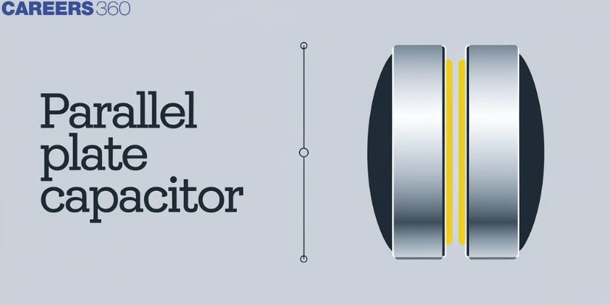
Parallel Plate Capacitor - Formula, Definition, Derivation, FAQs
A parallel plate capacitor consists of a plate connected to the positive end of a cell and another plate connected to the negative end or earthed. But let us first understand what a capacitor means. A capacitor consists of 2 conducting surfaces that are separated by a layer of an insulating medium also called a dielectric. This dielectric can be any insulating medium, the most common being parallel plate capacitors with air between the plates. The capacity of a conductor can be defined as the ratio between the charge on the conductor to its potential.

What is a Parallel Plate Capacitor?
A parallel plate capacitor consists of electrodes arranged along with some insulating material or dielectric. A parallel plate capacitor can store only a finite energy before dielectric breakdown occurs. Thus, we can say that Two parallel plates, when connected across a battery, get charged on account of an electric field existing between them and is known as a parallel plate capacitor.
Parallel Plate Capacitor Formula
The path of the electric field is defined as the path on which a positive test charge would move. The capacitance of the body is the measure of its ability to accumulate electric charge. Each capacitor has a capacitance. A typical parallel-plate capacitor has two metallic plates having area A, which are separated from each other by distance d.
The parallel plate capacitor formula is given by:
$$
C=k \epsilon_0 \frac{A}{d}
$$
Where,
$\epsilon_0$ is the permittivity of space $\left(8.854 \times 10^{-12} \mathrm{~F} / \mathrm{m}\right)$
$k$ is the relative permittivity of dielectric material
$d$ is the separation between the plates
A is the area of plates
Also, read
- NCERT Solutions for All Subjects
- NCERT Notes For All Subjects
- NCERT Exemplar Solutions for All Subjects
Units of Capacitance
In the S.I. unit, capacitance is measured in Farad (F).
$1 \mathrm{~F}=1$ Coulomb of charge/1 volt of potential
(By equation 1) we can define 1 Farad as - the capacity of a conductor is 1 F if a charge of 1 Coulomb is required to establish a p.d. of 1 Volt between the plates.
In the C.G.S. unit, capacitance is measured in stat farad.
Dimensional formula of capacitance is $\left[M^{-1} L^{-2} T^4 A^2\right]$.
Related Topics |
Parallel Plate Capacitor Derivation
An arrangement of parallel plates as shown in the following diagram depicts a parallel plate capacitor. This comprises two large plates aligned parallel to each other and placed at a small distance $d$ apart. Filling the gap between the plates is a dielectric material, which is shown in the dotted array. The two plates carry an equal and opposite charge.

This shows the first plate which is charged by +Q and by -Q on the second one. Each of the plates has an area A, while d is the distance between these plates. The distance $d$ is much smaller than the area of the plates and we can write $\mathrm{d}<<\mathrm{A}$, thus the effect of the plates is considered as infinite plane sheets and the electric field generated by them is treated as that equal to the electric field generated by an infinite plane sheet of uniform surface charge density. Thus, as the plate is 1 charge Q, and as the plate has surface area A, the surface charge density may be expressed as:
$$
\sigma=\frac{Q}{A}
$$
Similarly, for plate 2 with a total charge equal to -Q and area A, the surface charge density can be given as,
$$
\sigma=-\frac{Q}{A}
$$
We divide the regions around the parallel plate capacitor into three parts, with region 1 being the area left to the first plate, region 2 is the area between the two plates and region 3 being the area to the right of plate 2.
Let us calculate the electric field in the region around a parallel plate capacitor.
Region I: The electric field strength produced by both the infinite plane sheets I and II is equal at all points in this region, but since both are in the opposite direction, the two forces cancel and the whole electric field is given as:
$E=\frac{\sigma}{2 \varepsilon}-\frac{\sigma}{2 \varepsilon}=0$
Region II: The electric fields produced owing to both sheets I and II in this part are directed in the same way and have the same magnitude. Hence, the overall result will be as follows,
$E=\frac{\sigma}{2 \varepsilon}+\frac{\sigma}{2 \varepsilon}=\frac{\sigma}{\varepsilon}$
Region III: Similar to the region I, here also the field strengths created due to both plane sheets I and II are equal, but their directions are opposite, resulting in the same as,
$E=\frac{\sigma}{2 \varepsilon}-\frac{\sigma}{2 \varepsilon}=0$
The electric potential difference across the capacitor can be calculated by multiplying the electric field and the distance between the planes, given as,
$$
V=E \times d=\frac{1}{\varepsilon} \frac{Q d}{A}
$$
The capacitance for the parallel plate capacitor can be given as,
$$
c=\frac{Q}{V}=\frac{\varepsilon_0 A}{d}
$$
Frequently Asked Questions (FAQs)
C=C1C2/(C1+C2) = 10×20/(10+20)=6.6 μF
Energy stored in the capacitor=area under given plot=(1/2)QV
It is the ratio of capacitance Cd of the capacitor with the dielectric as the medium to its capacitance Cv i.e. when capacitors are in vacuum.
K=Cd/Cv
Parallel plate circuits block DC current when placed in circuits.