Download Careers360 App
Power And Power Factor In AC Circuits

Power And Power Factor In AC Circuits

Edited By Vishal kumar | Updated on Jul 02, 2025 05:57 PM IST

Power and power factors are critical concepts in alternating current (AC) circuits, essential for understanding how electrical energy is utilized efficiently. Power in AC circuits can be classified into active power, reactive power, and apparent power, each representing different aspects of energy consumption and transfer. The power factor, a measure of how effectively electrical power is converted into useful work, is crucial in minimizing energy losses and optimizing the performance of electrical systems. In real life, improving the power factor in industrial and residential settings reduces electricity bills and enhances the longevity of electrical equipment. This article explores the intricacies of power and power factors in AC circuits and their significance in practical applications.

This Story also Contains
  1. Power in an AC Circuit
  2. Solved Examples Based on Power in an AC Circuit
  3. Example 1: Calculate power (in watts) when the rms value of voltage and current are 220v & 3A respectively. The phase between the voltage of the current is π4
  4. Summary
Power And Power Factor In AC Circuits

Power in an AC Circuit

Power in an AC circuit refers to the rate at which electrical energy is transferred by an electric circuit. In alternating current (AC) circuits, power is not as straightforward as in direct current (DC) circuits due to the oscillating nature of voltage and current. we can say that the voltage v = vm sinωt applied to a series RLC circuit drives a current in the circuit given by i = im sin(ωt + φ) where,

im=vmZ and ϕ=tan1(XCXLR)

So, the instantaneous power is equal to

Pinstantaneous =vi=(vmsinωt)×[imsin(ωt+ϕ)]

By applying trigonometric application we get,
Pinstaneous =vmi2[cosϕcos(2ωt+ϕ)]

If we calculate the average power, then the second term of RHS will become zero. Because it is time-dependent and during one complete cycle, the summation will become zero.

PAverage =vmim2cosϕ=vm2im2cosϕPAverage =VIcosϕPAverage =I2Zcosϕ

From the above equation we can see that the average power dissipated depends on the voltage and current and the cosine of the phase angle φ between them. The quantity cosφ is called the power factor.

Let us discuss the power factor for various cases

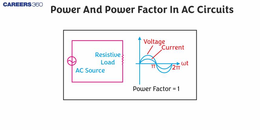
  • Resistive circuit: If in the circuit, only pure R is present, it is called resistive.circuit In that case φ = 0, because cos φ =1. And if the power factor is 1, then there is maximum power dissipation.
  • Purely inductive or capacitive circuit: From the previous concept and from the phasor diagram of these cases, we can say that, if the circuit contains only an inductor or capacitor then the phase difference between voltage and current is π2. Therefore, cos φ = 0, and no power is dissipated even though a current is flowing in the circuit. This current is referred to as a wattless current.
  • LCR series circuit: As we know the phase angle in this case is

φ=tan1XLXCR

So, maybe non-zero in R-L, R-C or R-L-C. And if it is non-zero, then there must be some power dissipation but that power dissipation is only in resistor.

  • The power dissipated at resonance in the LCR circuit: As we know at resonance,XCXL=0 , So, phase angle (φ) = 0. Therefore, cosφ = 1. So, P=I2Z=I2R. That is, maximum power is dissipated in a circuit at resonance. The total dissipation is through a resistor.
NEET Highest Scoring Chapters & Topics
This ebook serves as a valuable study guide for NEET exams, specifically designed to assist students in light of recent changes and the removal of certain topics from the NEET exam.
Download E-book

Apparent or Virtual Power

Apparent or virtual power in an AC circuit is the product of the root mean square (RMS) values of voltage and current. It represents the total power flowing through the circuit, combining both active (real) and reactive power. The product of apparent voltage and apparent current in an electrical circuit. Apparent power be always positive

Papp=Vrmsirms=v0i02

Recommended Topic Video

Solved Examples Based on Power in an AC Circuit

Example 1: Calculate power (in watts) when the rms value of voltage and current are 220v & 3A respectively. The phase between the voltage of the current is π4

1)466.76

2)660

3)330

4)233.38

Solution:

Average power (True power)

Pav=VrmsirmscosϕP=VrmsIrmscosϕ=220×3×cosπ4=466.76 W

Hence, the answer is the option (1).

Example 2: Find the average power generated (in watts) in the given circuit

1) 39.60

2)40.23

3)36.21

4)35.10

Solution:

Average power

Pav=irms2R=Vrms2RZ2Paverage =Irms2R=(Vrms)2RZ2R=0.2ΩXL=ωL=(2πf)L=2π×40×40×4×103=1ΩVrms=Vo2=2002Pav=(2002)2×0.2(12+(0.2)2)2=2×104×0.21.04=39.6 W

Hence, the answer is the option (1).

Example 3: Calculate the power factor in a given circuit

1) 1

2) 2

3) 4

4) 0

Solution:

The power factor in resistive circuits

cosϕ=1

Power factor
cosϕ=RZ
R=2kΩZ=R2+(XLXC)2=R(XL=XC=0)cosϕ=1 Power factor =1

Hence, the answer is the option (1).

Example 4: The current in a coil of self-inductance 2H is increasing according to I=2sin(t2)A. The amount of energy spent during the period when the current changes from 0 to 2 A is__________ J.

1)4

2)5

3)3

4)7

Solution:

e=|L(didt)|=2×2[cos(t2)]2te=8[cos(t2)]t

Energy dU= eidt
dU=16tsin(t2)cos(t2)dt
dU=8tsin(2t2)dt
When
Put ,2t2=xI=0,t2=04tdt=dxx=0dU=0π2sin(x)dxI=2,t2=π2x=π
U=2[cosx]0π=2(cosπ(cos0))U=4 J

Hence, the answer is the option (1).

Example 5:

Given that the peak voltage of the circuit is 200 V & rms value of the current is 20mA. Find the power consumed (in watts) by the circuit. (give the answer to 2 decimal places)

1) 2.82

2)3.46

3)2.01

4)1.82

Solution:

Power consumption
P=vrmsirms=12v0io Power consumed =VoIo2Irms=20 mAI0=2IrmsP=Vo2×2Irms=2002×2×20×103P=2.82

Hence, the answer is the option (1).

Summary

In AC circuits, power can be classified into active, reactive, and apparent power, each representing different aspects of energy transfer and consumption. The power factor, which measures how effectively electrical power is converted into useful work, is crucial in reducing energy losses and optimizing system performance. Real-life applications, such as improving the power factor in industrial and residential settings, help reduce electricity bills and enhance the longevity of electrical equipment. This article discusses the types of power in AC circuits, their calculation, and the importance of the power factor in practical applications.

Frequently Asked Questions (FAQs)

1. What is power in AC circuits?
Power in AC circuits is the rate at which electrical energy is transferred or consumed. It's the product of voltage and current, but in AC circuits, the relationship is more complex due to the constantly changing values of voltage and current over time.
2. How does power in AC circuits differ from power in DC circuits?
In DC circuits, power is simply voltage multiplied by current. In AC circuits, power calculation must account for the phase difference between voltage and current, leading to the concepts of real power, reactive power, and apparent power.
3. What is the power factor in AC circuits?
The power factor is the ratio of real power to apparent power in an AC circuit. It represents the efficiency of power transfer and is expressed as a number between 0 and 1, or as a percentage.
4. Why is a high power factor desirable in AC circuits?
A high power factor (close to 1) is desirable because it indicates efficient power transfer. It means that most of the apparent power is being converted to useful work (real power), minimizing wasted energy and reducing electrical system losses.
5. What causes a low power factor?
A low power factor is typically caused by inductive loads like motors or transformers. These devices create a phase shift between voltage and current, resulting in reactive power that doesn't do useful work but still needs to be supplied by the power source.
6. How does the concept of power factor apply to energy storage systems like batteries?
Energy storage systems, when charging or discharging, can affect the overall power factor of a system. Advanced battery management systems often include power factor correction capabilities to ensure smooth integration with the grid.
7. What is the significance of a unity power factor?
A unity power factor (exactly 1.0) represents the ideal situation where all power supplied is converted to useful work. In this case, voltage and current are perfectly in phase, and there is no reactive power in the circuit.
8. How does power factor affect the sizing of electrical equipment?
A low power factor requires electrical equipment (like generators, transformers, and wiring) to be sized larger to handle the higher apparent power and current, even if the real power demand remains the same. This increases installation and operating costs.
9. What is the relationship between power triangle and power factor?
The power triangle is a visual representation of the relationship between real power, reactive power, and apparent power. The power factor is represented by the cosine of the angle between the apparent power and real power vectors in this triangle.
10. How does the concept of power factor apply to renewable energy systems connected to the grid?
Grid-connected renewable energy systems must often meet specific power factor requirements set by utility companies. Inverters used in these systems typically have the capability to adjust their power factor to support grid stability and comply with interconnection standards.
11. How do transformers impact power factor?
Transformers, being inductive devices, typically cause a lagging power factor. They consume reactive power to create their magnetic fields, which can lower the overall power factor of a system if not compensated for.
12. How do electric motors affect power factor?
Electric motors, particularly induction motors, are inductive loads that typically cause a lagging power factor. When starting, motors can significantly lower the power factor of a system due to the high inrush current and increased reactance.
13. How do renewable energy sources like solar panels affect power factor?
Solar inverters used with photovoltaic systems can introduce power factor issues, particularly when operating at partial capacity. Modern inverters often include power factor correction capabilities to mitigate these effects and comply with grid requirements.
14. How does temperature affect power factor in electrical equipment?
Temperature can indirectly affect power factor by altering the characteristics of electrical components. For example, the resistance of conductors increases with temperature, which can impact the overall impedance and potentially the power factor of the system.
15. How does power factor correction affect harmonic distortion?
While basic power factor correction can improve the fundamental power factor, it may sometimes exacerbate harmonic distortion. Advanced power factor correction techniques can be designed to simultaneously improve power factor and reduce harmonics.
16. How do variable frequency drives (VFDs) impact power factor?
VFDs can significantly improve the power factor of motor-driven systems by controlling the motor's speed and torque more efficiently. However, they can also introduce harmonics, which may require additional filtering or more advanced power factor correction techniques.
17. How does capacitance affect power factor?
Capacitance can improve power factor in circuits with inductive loads. Capacitors store energy in their electric field during part of the AC cycle and release it later, helping to balance out the effects of inductance and bringing the current more in phase with voltage.
18. What is the difference between real power and reactive power?
Real power (measured in watts) is the power that actually does work or is converted to other forms of energy. Reactive power (measured in volt-amperes reactive or VAR) is power that oscillates between the source and the load without doing useful work.
19. How is apparent power related to real and reactive power?
Apparent power is the vector sum of real and reactive power. It represents the total power supplied by the source and is calculated using the Pythagorean theorem: Apparent Power² = Real Power² + Reactive Power².
20. Why do we need to consider reactive power in AC circuits?
Reactive power, although not doing useful work, is necessary for creating magnetic fields in inductive devices like motors and transformers. It's crucial for their operation and must be supplied by the power source, impacting overall system efficiency.
21. How can you improve a low power factor?
Power factor can be improved by adding capacitors to the circuit (power factor correction), replacing old motors with high-efficiency ones, or using electronic power factor correction devices. These methods aim to bring the current more in phase with voltage.
22. How does power factor affect electricity bills?
Many utility companies charge extra for low power factor because it requires them to generate more power than is actually used. Improving power factor can lead to lower electricity bills for industrial and commercial consumers.
23. What is the relationship between power factor and phase angle?
The power factor is equal to the cosine of the phase angle between voltage and current. As the phase angle increases, the power factor decreases, indicating less efficient power transfer.
24. Can power factor ever be negative?
Yes, power factor can be negative in situations where power is being fed back into the grid, such as with certain types of renewable energy systems or regenerative braking in electric vehicles.
25. How does frequency affect power in AC circuits?
Frequency doesn't directly affect power calculations, but it can influence the behavior of reactive components like inductors and capacitors, potentially impacting the overall power factor of the circuit.
26. What is the difference between leading and lagging power factor?
A leading power factor occurs when current leads voltage in phase, typically in capacitive circuits. A lagging power factor occurs when current lags behind voltage, usually in inductive circuits. Most electrical loads have a lagging power factor.
27. What is power factor correction?
Power factor correction is the process of improving the power factor of an AC circuit, typically by adding capacitance to counteract the effects of inductive loads. This brings the current more in phase with voltage, increasing efficiency.
28. Why don't we use power factor correction in all AC circuits?
Power factor correction isn't always necessary or cost-effective, especially in small-scale residential applications. It's most beneficial in industrial settings with large inductive loads where the energy savings can offset the cost of correction equipment.
29. How does power factor affect the current drawn from a power source?
A low power factor increases the current drawn from the power source for the same amount of real power delivered. This higher current leads to increased power losses in transmission lines and can require larger, more expensive electrical equipment.
30. What is the relationship between power factor and efficiency?
While power factor and efficiency are related, they're not the same. A high power factor indicates efficient power transfer, but overall system efficiency also depends on other factors like resistive losses and the efficiency of the load devices themselves.
31. What is the impact of harmonics on power factor?
Harmonics in AC circuits can distort the relationship between voltage and current, leading to a reduced power factor. They can also cause additional heating in electrical equipment and interfere with power factor correction efforts.
32. How is power factor measured in practice?
Power factor is typically measured using specialized power factor meters or power quality analyzers. These devices measure both the real power and apparent power in the circuit and calculate the power factor from these values.
33. What is the difference between displacement power factor and true power factor?
Displacement power factor considers only the fundamental frequency components of voltage and current. True power factor takes into account the effects of harmonics as well. In circuits with significant harmonic content, these two values can differ substantially.
34. What is the significance of reactive power compensation?
Reactive power compensation, often achieved through capacitor banks or static VAR compensators, helps maintain voltage stability in power systems, reduces losses, and improves overall system efficiency by managing the flow of reactive power.
35. How does power factor vary throughout the day in a typical electrical system?
Power factor in electrical systems can vary throughout the day based on the changing load characteristics. For example, it might be lower during peak hours when more inductive loads (like air conditioners and industrial equipment) are operating.
36. What is the impact of a low power factor on voltage regulation?
A low power factor can lead to poor voltage regulation in power systems. The increased current draw associated with low power factor can cause larger voltage drops along transmission lines, potentially leading to unstable voltages at the point of use.
37. What is the difference between active and passive power factor correction?
Passive power factor correction typically involves adding capacitors to the circuit to counteract inductive loads. Active power factor correction uses electronic circuits to dynamically adjust the power factor, offering more precise control but at a higher cost.
38. What is the significance of the 0.9 power factor threshold often mentioned in electrical standards?
Many electrical codes and utility companies set 0.9 as a minimum acceptable power factor. This threshold represents a balance between efficient power use and the practical limitations of power factor correction in real-world systems.
39. How does the concept of power factor apply to three-phase systems?
In balanced three-phase systems, power factor calculations are similar to single-phase systems but consider the total power across all three phases. Unbalanced three-phase systems require more complex analysis, considering the power factor of each phase separately.
40. What is the relationship between power factor and the direction of power flow?
The sign of the power factor (positive or negative) indicates the direction of power flow. A positive power factor indicates power flowing from the source to the load, while a negative power factor suggests power flowing from the load back to the source.
41. How do electronic loads like computers and LED lights affect power factor?
Many electronic loads use switch-mode power supplies that can introduce harmonic distortion and affect power factor. Modern designs often incorporate power factor correction circuits to mitigate these effects and comply with energy efficiency standards.
42. What is the impact of power factor on the lifespan of electrical equipment?
A low power factor can lead to increased current flow, potentially causing more heat generation in electrical equipment. This additional heat can accelerate aging and reduce the lifespan of components like transformers, motors, and wiring.
43. What is the relationship between power factor and reactive power consumption in industrial settings?
In industrial settings with large inductive loads, there's often a direct relationship between low power factor and high reactive power consumption. Improving power factor through correction techniques can significantly reduce the reactive power demand from the utility.
44. How does power factor affect the efficiency of power transmission over long distances?
A low power factor increases the current required to transmit a given amount of real power, leading to higher I²R losses in transmission lines. This reduces the overall efficiency of power transmission, especially over long distances.
45. What is the significance of leading power factor in certain applications?
While most loads exhibit a lagging power factor, a leading power factor can be beneficial in some cases. For example, it can help counteract the lagging power factor of nearby inductive loads or assist in voltage regulation in long distribution lines.
46. What is the relationship between power factor and the concept of "volt-ampere reactive hours" (VARh) in utility metering?
VARh is a measure of reactive energy over time, similar to kWh for real energy. Utilities may use VARh metering to charge for excessive reactive power consumption, which is directly related to low power factor. Improving power factor can reduce VARh charges.
47. How does the power factor of individual loads affect the overall power factor of a facility?
The overall power factor of a facility is a weighted average of the power factors of individual loads. Large loads with poor power factors have a more significant impact on the facility's overall power factor, often necessitating correction at the facility level.
48. What is the impact of power factor on the selection of circuit breakers and fuses?
Low power factor increases the current flow for a given amount of real power, which may require larger-rated circuit breakers and fuses. This can increase the cost of electrical installations and potentially impact the coordination of protective devices.
49. What is the relationship between power factor and the concept of "demand charges" in commercial electricity billing?
Demand charges are based on the peak power demand, which is influenced by both real and reactive power. A low power factor can increase the apparent power and thus the peak demand, potentially leading to higher demand charges on electricity bills.
50. How does the improvement of power factor contribute to overall energy efficiency and sustainability goals?
Improving power factor reduces losses in electrical systems, decreases the need for oversized equipment, and can lower overall energy consumption. This contributes to energy efficiency goals, reduces carbon emissions associated with electricity generation, and supports broader sustainability initiatives in electrical power systems.
Induced Electric Field

02 Jul'25 07:40 PM

Faraday's law of induction

02 Jul'25 06:23 PM

Time Varying Magnetic Field

02 Jul'25 06:05 PM

Self Inductance

02 Jul'25 06:05 PM

Mutual Inductance

02 Jul'25 06:05 PM

Series LR Circuit

02 Jul'25 05:58 PM

Articles

Back to top