

Quality Factor In An AC Circuit
The quality factor, or Q factor, in an AC circuit is a dimensionless parameter that measures the efficiency and performance of a resonant circuit. It indicates how underdamped the circuit is and is defined as the ratio of the resonant frequency to the bandwidth over which the circuit resonates. A higher Q factor signifies lower energy loss relative to the stored energy, leading to sharper resonance and better selectivity. In real life, the quality factor is crucial in designing filters and oscillators in radios, televisions, and other communication devices, ensuring clear signal reception and transmission by minimizing energy loss and enhancing performance. This article explores the significance, calculation, and practical applications of the quality factor in AC circuits.
This Story also Contains
- Quality Factor
- Solved Examples Based on Quality Factor In an AC Circuit
- Example 1: The q factor depends on which of the following?
- Summary
Quality Factor
The quality factor, or Q factor, in an AC circuit, is a measure of how efficiently the circuit stores energy versus how much energy it loses. It is a dimensionless parameter that indicates the sharpness of resonance in a resonant circuit. The ratio of the resonant frequency to the bandwidth over which the circuit resonates, a higher Q factor means the circuit has lower energy loss relative to the energy stored.
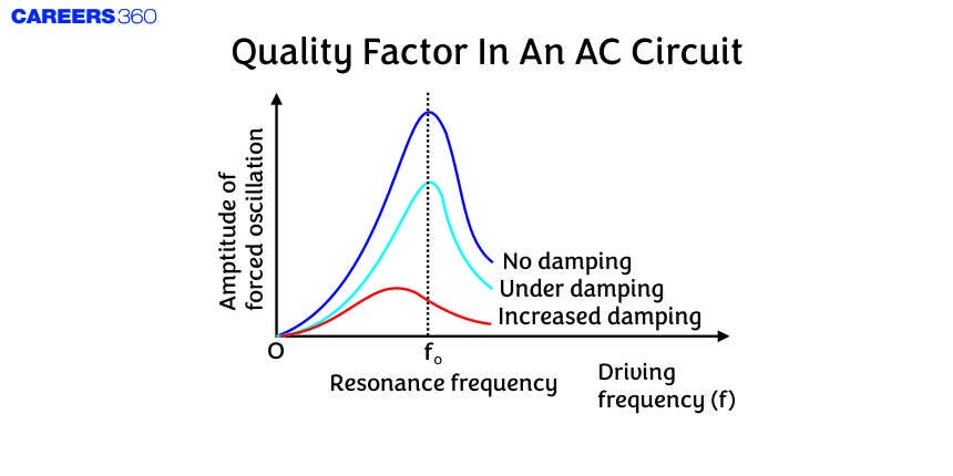
The quality factor Q is a parameter which is used to describe the sharpness of the resonance curve. So it is defined as the ratio of voltage drop across the inductor or capacitor at resonance to the applied voltage. So,
$\begin{gathered}Q=\frac{\text { Voltage across } L \text { or } C \text { at resonance }}{\text { Applied voltage }} \\ Q=\frac{I_v \omega_o L}{I_v R}=\omega_o \frac{L}{R}\end{gathered}$ As we know, at the resonance
$\omega_o=\frac{1}{\sqrt{L C}}$
So,
$Q=\frac{1}{R} \sqrt{\frac{L}{C}}$
We can also say that the characteristic of a series resonant circuit is determined by the quality factor (Q - factor) of the circuit. So, if the value of the Q-factor is high then the sharpness of the resonant curve is more and vice-versa.
We can also define the Q -factor which is defined as $2 \pi$ times the ratio of the energy stored in L or C to the average energy loss per period. So,
$Q=2 \pi\left[\frac{\text { Maximum energy stored in the capacitor }}{\text { Energy loss per period }}\right]$
Now, the maximum energy stored in the inductor
$U=\frac{1}{2} L\left(I_o\right)^2$
Also, the energy dissipated per second
$P_R=I_{r m s}^2 R=\frac{I_o^2 R}{2}$
The energy dissipated per time period
$U_R=\frac{I_o^2 R}{2} \times T$
Putting all these in the (1)
$Q=\frac{1}{R} \sqrt{\frac{L}{C}}$
The Q-factor of the circuit varies inversely as R. Thus, at resonance, the voltage drop across inductance or capacitance is Q-times the applied voltage.

From the graph, we can see that when the Q-factor tends to infinity, then the current becomes infinite. And as the Q-factor become very low then the amplitude of the current will become very low.
In an AC circuit, If,
$\begin{gathered}R=0 \text { or } \cos \phi=0 \\ P_{a v}=0\end{gathered}$
Wattless Current
In a resistance-less circuit the power consumed is zero such a circuit is called wattless and the current following is called wattless current.
The amplitude of Wattless is $I_0 \sin \varphi$
Recommended Topic Video
Solved Examples Based on Quality Factor In an AC Circuit
Example 1: The q factor depends on which of the following?
1)Inductance & Capacitance
2)Resistance & Capacitance
3)Inductance & Resistance
4)Inductance, Capacitance & Resistance
Solution:
$\begin{aligned} & \text { Q-factor }=\frac{\text { resonant frequency }}{\text { band width }}=\frac{\omega_0}{\delta \omega} \\ & \text { Q-factor is given as }=\frac{1}{R} \sqrt{\frac{L}{C}}\end{aligned}$
Hence, the answer is the option (1)
Example 2: For an RLC circuit driven with the voltage of amplitude vm and frequency $\omega_o=\frac{1}{\sqrt{L C}}$ the current exhibits resonance. The quality factor, Q is given by :
1) $\frac{C R}{\omega_o}$
2) $\frac{\omega_o L}{R}$
3) $\frac{\omega_o R}{L}$
4) $\frac{R}{\left(\omega_o C\right)}$
Solution:
$\begin{aligned} & \text { Q factor } \\ & \begin{array}{l}\frac{V_L}{V_R} o r \frac{V_c}{V_R}=\frac{\omega_0 L}{R} o r \frac{1}{\omega_0 c R} \\ \text { Quality Factor } \mathrm{Q}=\frac{w_0}{w_2-w_1} \\ \qquad w_2-w_1=\frac{R}{L} \\ \quad \Rightarrow Q=\frac{w_o L}{R}\end{array}\end{aligned}$
Hence, the answer is the option (2).
Example 3:

The Q-factor of the circuit is
1) 22.36
2)15.3
3)40.1
4)18.10
Solution:
Q factor
$\begin{aligned} & \frac{1}{R} \sqrt{\frac{L}{C}} \\ & \text { wherein } \\ & \text { L-inductance } \\ & \text { C-capacitance } \\ & Q=\frac{1}{0.2} \sqrt{\frac{10}{0.5}} \\ & Q=22.36\end{aligned}$
Hence, the answer is the option (1).
Example 4: A wattless current is flowing in a circuit whose peak value is 4 mA and the phase between voltage and current is $\frac{\pi}{2}$. Find the amplitude of the wattless current. (in mA)
1) 4
2)2
3)1
4)8
Solution:
The amplitude of wattless current $=\mathrm{I}_0 \sin \phi=4 \sin \frac{\pi}{2}$
Amplitude $=4 \mathrm{~mA}$
Hence, the answer is the option (1).
Example 5: The plot given below is of the average power delivered to an LRC circuit versus frequency. the quality factor of the circuit is:

1) 2
2)5
3)2.5
4)0.4
Solution:
From the graph,
Resonating frequency, [ $\omega_0=5 \mathrm{KHz}$ (at which peak occurs)]
and
Bandwidth, $(2 \Delta w)=2.5 \mathrm{KH}_z$ (frequency difference when power in half of peak)
So quality factor,
$$
Q=\frac{w_0}{2 \Delta w}=\frac{5}{2.5}=2
$$
Hence, the answer is the option (1).
Summary
The quality factor (Q factor) in an AC circuit measures the efficiency and performance of a resonant circuit, indicating how underdamped the circuit is. It is defined as the ratio of the resonant frequency to the bandwidth over which the circuit resonates. A higher Q factor signifies lower energy loss relative to the stored energy, leading to sharper resonance and better selectivity. This is crucial in designing filters and oscillators in communication devices, ensuring clear signal reception and transmission. Calculations and solved examples illustrate its dependence on circuit components and its impact on energy dissipation and resonance behaviour.
