

Voltmeter
A voltmeter is an essential instrument used to measure the voltage, or electrical potential difference, between two points in an electric circuit. Think of it like a pressure gauge in a water system; just as a pressure gauge tells us how much force is driving water through pipes, a voltmeter tells us how much "electrical pressure" is pushing electrons through a conductor. In our daily lives, voltmeters play a crucial role in everything from ensuring the proper functioning of household appliances to maintaining the safety of electrical systems in vehicles and industrial machines. Whether it's checking the health of a battery, diagnosing electrical issues in a circuit, or designing sophisticated electronic devices, the voltmeter is a critical tool that helps engineers and technicians keep our electrically powered world running smoothly. In this article, we will discuss the concept of Voltmeter. It quantifies potential differences over components thereby laying bare invisible forces powering electric currents, which makes it a crucial tool for anyone seeking to understand circuits or diagnose electrical defects.
This Story also Contains
- Voltmeter
- Solved Examples Based on Voltmeter
- Summary

Voltmeter
A voltmeter is a fundamental device used to measure the voltage, or electrical potential difference, between two points in an electrical circuit. Just as a thermometer measures temperature or a speedometer measures speed, a voltmeter provides a direct reading of the "pressure" that drives electric current through a circuit.

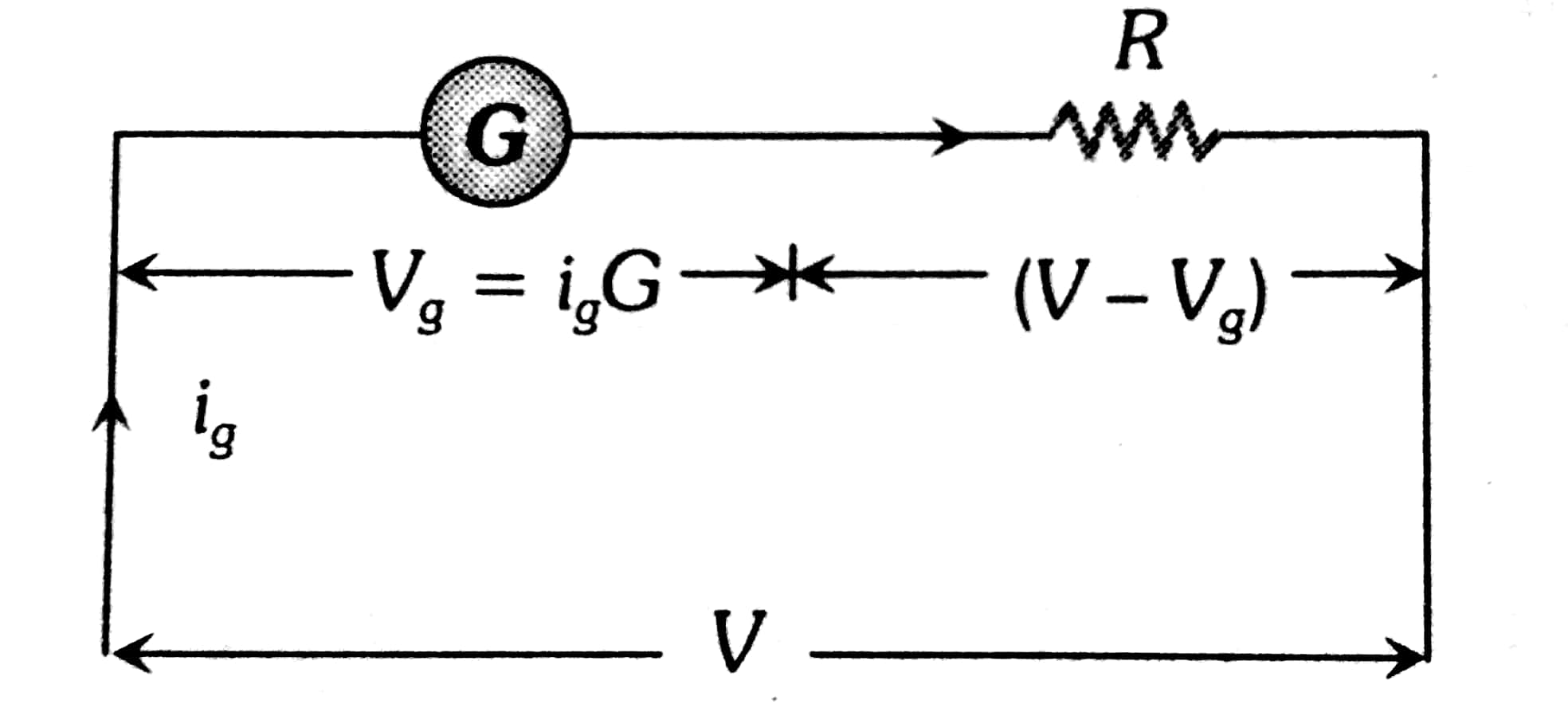
Convert the galvanometer into a voltmeter by connecting a large series of resistances.

The equivalent resistance of the combination is $G+R$
The required value of high resistance to be connected in series with the galvanometer is $R=\frac{V}{I_g}-G=\left[\frac{V}{V_g}-1\right] G$. V is the total voltage applied across the circuit and $V_g$ is the total voltage drop across the galvanometer.
if $n^{t h}$ part of the applied voltage across the galvanometer, that is $V_g=V / n$, then $R=(n-1) G$.
Recommended Topic Video
Solved Examples Based on Voltmeter
Example 1: A galvanometer has a resistance of $30 \Omega$ and a current of 2mA is needed for a full-scale deflection. The resistance $($ in $\Omega)$ that should be used to convert it into a voltmeter of 0.2V range is
1) 70
2) 60
3) 80
4) 90
Solution:
Conversion of galvanometer into voltameter
Connected a large Resistance R in a series
wherein
To convert galvanometer into voltmeter of 0.2V range
$
\begin{aligned}
& V=I_g \cdot(R+G) \\
& \Rightarrow 0.2=2 * 10^{-3} *(30+R)
\end{aligned}
$
or $R=70 \Omega$
Hence, the answer is the option (1).
Example 2: A moving coil galvanometer allows a full-scale current of $10^{-2}$ A. A series resistance of $200 \Omega$ is required to convert the above galvanometer into a voltmeter of range0-5 V . Therefore the value of shunt resistance $(\operatorname{in} \Omega)$ required to convert the above galvanometer into an ammeter of range0-10 mA is :
1) 300
2) 100
3) 200
4) 10
Solution:
Conversion of galvanometer into voltameter
Connected a large Resistance in a series
wherein
$\begin{aligned} & (\mathrm{R}+\mathrm{G}) \mathrm{I}=\mathrm{V} \\ & \left(2 \times 10^2+G\right) 10^{-2}=V=5 \\ & =2+10^{-2} G=5 \\ & \mathrm{G}=300 \Omega\end{aligned}$
Hence, the answer is the option (1).
Example 3: A moving coil galvanometer has resistance $50 \Omega$ and it indicates full deflection at $4 m A$ current. A voltmeter is made using this galvanometer and a $5 k \Omega$ resistance. The maximum voltage (in V), that can be measured using this voltmeter, will be close to :
1) 20.2
2) 15
3) 40
4) 10
Solution:
Conversion of galvanometer into voltameter
Connected a large Resistance R in a series
wherein
Given $G=50 \Omega$
$
i_g=4 m A
$
Series resistance $\quad S=5 k \Omega$
$
\begin{aligned}
V & =i_g(G+S) \\
& =4 \times 10^{-3}(5000+50) \\
& =20.2 \mathrm{~V}
\end{aligned}
$
Hence, the answer is the option (1).
Example 4: A 100V voltmeter having an internal resistance of $20 \mathrm{k} \Omega$.. is connected in series with a large resistance R across a 110V line. If the voltmeter reads 5V then the magnitude of R (in $k \Omega$ ) is
1) 420
2) 210
3) 110
4) 630
Solution:
Equivalent resistance

$\begin{aligned} & V_R=110-5=105 \mathrm{~V} \\ & \frac{V_R}{V_1}=\frac{R}{R_1} \text { i.e } \frac{105}{5}=\frac{R}{20 k \Omega} \\ & R=420 k \Omega\end{aligned}$
Hence, the answer is the option (1).
Example 5: Two resistors $400 \Omega$ and $800 \Omega$ are connected in series across a 6 V battery. The potential difference measured by a voltmeter of $10 k \Omega$ across $400 k \Omega$resistor is close to :
1) 2 V
2) 1.8 V
3) 2.05 V
4) 1.95 V
Solution:
From the question
The circuit diagram is drawn as shown below

$\begin{aligned} & i=\frac{6}{800+\left(\frac{40 \times 100000}{400+100000}\right)} \\ & i=\frac{6}{1184.61}=0.00506 \\ & V_{A B}=6-(800 \times 0.00506)=6-4.05=1.95\end{aligned}$
Hence, the answer is the option (4).
Summary
A voltmeter is a crucial device for measuring the voltage across components in an electrical circuit, providing insights into the electrical potential differences that drive current. It is often created by converting a galvanometer through the addition of a high resistance in series. This allows it to measure voltage accurately without significantly altering the circuit it is testing. Understanding how to convert a galvanometer into a voltmeter and solve related problems is essential for diagnosing and analyzing electrical circuits effectively.
