Difference Between Series and Parallel Circuits - A Complete Guide

Difference Between Series and Parallel Circuits - A Complete Guide

Team Careers360Updated on 02 Jul 2025, 05:04 PM IST

Introduction
In this chapter, we will study in depth the difference between series and parallel circuit, series connection, series connection diagram. We will also study parallel circuits and compare series and parallel circuits. Later on, we will try to understand series parallel circuits and study about series and parallel connection. In the Last we will study resonance and relate it with Series and Parallel circuits.

This Story also Contains

  1. What is a Series Circuit?
  2. What is a Parallel Circuit?
  3. Write the difference between series connection and parallel connection :
Difference Between Series and Parallel Circuits - A Complete Guide
Difference Between Series and Parallel Circuits

What is a Series Circuit?

We have broadly classified the arrangement of electrical network having two endpoints into two parts, namely:

Series Connection

Parallel Connection

Also read -

Electric Circuit

An Electric Circuit is a path for transmitting Electric Current comprising battery(source of current),device that uses current( electric bulb, lamp).
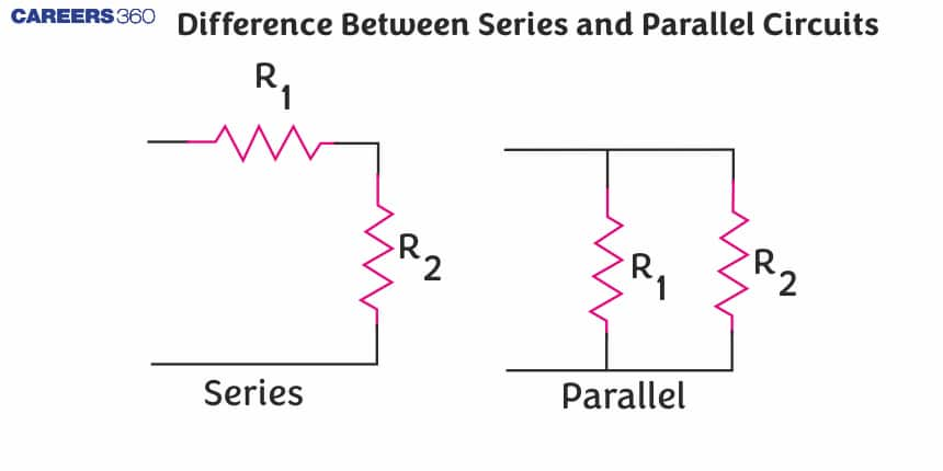
Series Connection

In the series combination, each circuit component is arranged in series. In Series connection, there is only one direction in which current flows, thus opening or breaking of any part in the circuit leads to the failure of the flow of current.

Properties

  • In series combination, the same current flows through each component of the circuit, hence the magnitude of current remains the same across the ends of the circuit.

Or, numerically it is given as

I=i(1)=i(2)=i(3)=i(4)……………..

  • But, the voltage across the circuit is the sum of the individual voltage drop across each component of the circuit.
NEET Highest Scoring Chapters & Topics
This ebook serves as a valuable study guide for NEET exams, specifically designed to assist students in light of recent changes and the removal of certain topics from the NEET exam.
Download E-book

Or, numerically it is given as

V= v(1)+v(2)+v(3)+v(4)……………….

Commonly Asked Questions

Q: How does the concept of equivalent resistance differ between series and parallel circuits?
A:
In series circuits, equivalent resistance is the sum of individual resistances. In parallel circuits, equivalent resistance is always less than the smallest individual resistance and is calculated using the reciprocal formula.
Q: Why do batteries last longer in a parallel circuit than in a series circuit?
A:
In a parallel circuit, each component draws current independently, so the total current from the battery is divided. In a series circuit, all components draw the same current, which can drain the battery faster.
Q: How does a short circuit affect current flow in series and parallel circuits?
A:
In both series and parallel circuits, a short circuit provides a path of very low resistance, causing a large increase in current flow. This can be dangerous and may damage components or cause fires if not properly protected.
Q: How does the power consumption of a device change when switched from series to parallel connection?
A:
When switched from series to parallel, a device typically consumes more power. This is because in parallel, it receives full voltage, while in series, it receives only a fraction of the total voltage.
Q: What is the advantage of using a parallel circuit for a string of LED holiday lights?
A:
In a parallel circuit of LED holiday lights, if one LED fails, the others continue to work. This is more convenient and safer than traditional series-wired lights where one failure causes the entire string to go dark.

What is a Parallel Circuit?

In a parallel circuit, two or more electrical components are arranged parallel to each other. In this combination, unlike the series combination, there is more than one direction in which current flows.

Properties

  • Potential difference across the components of the circuit remains the same.

V=v(1)=v(2)=v(3)=v(4)…………

  • Magnitude of current is equal to the total sum of current across the electric circuit.

I=i(1)+i(2)+i(3)+i(4)+……………..

Series and parallel circuit diagram:

ab

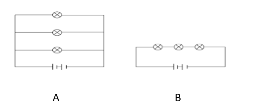
In this diagram, the connection parallel and the series circuit is shown as A and B respectively.

Also read :

Commonly Asked Questions

Q: What happens to the current in a parallel circuit if one branch is disconnected?
A:
If one branch in a parallel circuit is disconnected, the current in that branch stops, but current continues to flow through the other branches. The total current from the source decreases, but the voltage across the remaining branches stays the same.
Q: How does adding resistors in parallel affect the total resistance?
A:
Adding resistors in parallel decreases the total resistance. The total resistance is calculated using the reciprocal formula: 1/R_total = 1/R1 + 1/R2 + 1/R3 + ...
Q: Why are household electrical outlets wired in parallel?
A:
Household outlets are wired in parallel to ensure that each device receives the full voltage from the power source and can operate independently. This allows you to turn one device on or off without affecting others.
Q: Why are car headlights connected in parallel rather than in series?
A:
Car headlights are connected in parallel so that if one fails, the other continues to work. In a series connection, if one headlight failed, both would go out, creating a dangerous driving situation.
Q: How does the brightness of identical bulbs compare in series versus parallel circuits?
A:
In a parallel circuit, identical bulbs will be equally bright and at full brightness. In a series circuit, the bulbs will be dimmer than in parallel, and their brightness may vary if the resistances are not identical.

Write the difference between series connection and parallel connection :

In the above figure, A represents a parallel connection diagram. In the Figure, we can clearly see all three Resistors are placed parallel to each other and the voltage source is also placed parallel to that combination. Hence there is a different path for the flow of the current and thus there will be the distribution of the current along each path.

While Looking at Figure (B), we can clearly see all the resistors are placed in sequential order thus forming the same path for the flow of the current leading to the same current flow through each resistor.

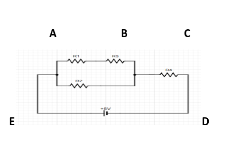
Series Parallel Circuit

abcd

Till now we have studied series and parallel as two different combinations but can we combine these two combinations as a single arrangement?

Yes, the answer to that is that we can arrange both these combinations as a single arrangement.

NOTE: This is valid till the loop formed is always closed.

In the above diagram, we can clearly see two different paths for which current can take

NCERT Physics Notes :

Arrangement:

  • Series Combination of R(1) and R(2) with a parallel combination of R(3).
  • Combination or Resultant of R(1), R(2), R(3)in series with R(4).

Resonance

Resonance is an electrical phenomenon, occurring if capacitors and inductors are present in the electric circuit. Resonance happens when the capacitive impedance is equal to inductive impedance. There is a difference in the arrangement of capacitors and inductors in series and parallel circuit

  • In series, both capacitors and inductors are arranged in series
  • While, in parallel circuit capacitors and inductor is placed parallel to each other.

Variation in result:

  • Series resonance occurs when the impedance formed is Minimum
  • Parallel resonance occurs when the impedance formed is Maximum

Voltage in Series and Parallel circuit

  • In series connection voltage across the circuit changes.It is the sum of the individual voltage across the components of the circuit.
  • While in a parallel circuit, voltage across different components placed in the different loop of the circuit remains the same. It does not change.

Power in Series and Parallel

  • Power in series gets distributed across resistors, hence total Power in a series circuit is equal to the sum of individual power across each resistor.
  • Since we know that voltage across resistors in parallel circuit is equal,so the power dissipated in the parallel circuit is given by the formula :

P= (Electric current)square(Electric Resistance)

Also check-

Commonly Asked Questions

Q: What is the fundamental difference between series and parallel circuits?
A:
In a series circuit, components are connected end-to-end in a single path, while in a parallel circuit, components are connected across multiple branches. This difference affects how current flows and how voltage is distributed in each type of circuit.
Q: How does current flow differ in series and parallel circuits?
A:
In a series circuit, the same current flows through all components. In a parallel circuit, the current divides among different branches, with the total current equal to the sum of currents in each branch.
Q: How is voltage distributed in series versus parallel circuits?
A:
In a series circuit, voltage is divided among the components, with the total voltage equal to the sum of individual voltage drops. In a parallel circuit, each component experiences the same voltage as the source.
Q: Why do Christmas lights often fail when one bulb burns out?
A:
Traditional Christmas lights are wired in series. When one bulb burns out, it breaks the circuit, preventing current from flowing through the entire string. Modern LED Christmas lights often use parallel wiring to avoid this issue.
Q: How does adding resistors in series affect the total resistance?
A:
Adding resistors in series increases the total resistance. The total resistance is the sum of individual resistances: R_total = R1 + R2 + R3 + ...

Frequently Asked Questions (FAQs)

Q: How does the concept of "fault tolerance" relate to the use of parallel circuits in critical systems?
A:
Parallel circuits in critical systems provide fault tolerance by allowing continued operation even if one component or path fails. This redundancy is crucial in applications where system reliability is paramount, such as in aerospace, medical, or industrial control systems.
Q: Why are some power transmission lines designed with multiple conductors in parallel?
A:
Multiple parallel conductors in power transmission lines reduce the overall resistance and inductance of the line, increasing its current-carrying capacity and reducing power losses. This design also helps in heat dissipation and can improve the mechanical strength of the line.
Q: How does the concept of "impedance matching" apply differently to series and parallel circuits in RF applications?
A:
In RF applications, series circuits are often used for impedance matching when the load impedance is lower than the source impedance. Parallel circuits are used when the load impedance is higher than the source impedance. The goal is to maximize power transfer and minimize signal reflections.
Q: What is the advantage of using parallel-connected supercapacitors in energy storage systems?
A:
Parallel connection of supercapacitors increases the total capacitance and energy storage capacity while maintaining the voltage rating. This allows for scalable energy storage solutions with rapid charge and discharge capabilities.
Q: How does the concept of "current sensing" differ in series versus parallel circuits?
A:
In series circuits, current sensing typically involves measuring the voltage drop across a low-value resistor in series with the load. In parallel circuits, current sensing might involve measuring the current in individual branches or using a hall-effect sensor around a conductor.
Q: Why are some battery management systems designed with a combination of series and parallel connections?
A:
Battery management systems use series connections to achieve higher voltages and parallel connections to increase capacity and distribute charging/discharging currents. This combination allows for optimized energy storage and delivery in various applications.
Q: How does the concept of a voltage divider circuit relate to series and parallel connections?
A:
A voltage divider circuit is a specific application of series-connected resistors, where the output voltage is a fraction of the input voltage. Parallel connections are not typically used for voltage division.
Q: Why are some high-power resistors connected in parallel rather than using a single large resistor?
A:
Connecting resistors in parallel distributes the power dissipation among multiple components, reducing heat concentration and improving overall thermal management. It also allows for the use of more commonly available resistor values.
Q: What is the significance of the "parallel plate" design in capacitors?
A:
The parallel plate design in capacitors increases the effective area of the conducting surfaces, which increases capacitance. This is analogous to connecting capacitors in parallel, which adds their individual capacitances.
Q: How does the concept of "equivalent circuit" differ for series and parallel combinations?
A:
An equivalent circuit for series combinations typically simplifies to a single higher-value component (e.g., resistor or inductor). For parallel combinations, it usually simplifies to a single lower-value component.