Download Careers360 App
Series RC Circuit

Series RC Circuit

Edited By Vishal kumar | Updated on Jul 02, 2025 05:58 PM IST

A Series RC circuit consists of a resistor (R) and a capacitor (C) connected in series, forming a fundamental component in electrical and electronic systems. When an AC voltage is applied, the circuit demonstrates unique behaviours in terms of charging and discharging the capacitor, as well as impedance. These characteristics are pivotal in various practical applications such as filtering signals, shaping waveforms, and timing circuits. In everyday life, series RC circuits are found in devices like audio equipment, where they help manage signal frequencies, and in-camera flashes, where they control the charging time of the flash capacitor. In this article, we will understand the dynamics of a Series RC circuit is essential for designing and optimizing electronic devices and systems.

This Story also Contains
  1. Series RC Circuit
  2. Important Points
  3. Solved Examples Based on Series RC Circuit
  4. Example 1: The susceptance of a circuit is
  5. Summary
Series RC Circuit
Series RC Circuit

Series RC Circuit

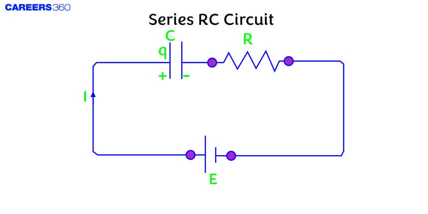
A Series RC circuit is a simple electrical circuit that comprises a resistor (R) and a capacitor (C) connected in series with each other. This type of circuit is widely used in various electronic applications due to its ability to store and release energy, filter signals, and create time delays.

The above figure shows a circuit containing a resistor and capacitor connected in series through a sinusoidal voltage source voltage which is given by

$V=V_0 \sin (\omega t+\varphi)$

Now, in this case, the voltage across the resistor is VR=IR

And, the voltage across the capacitor is

$V_c=\frac{I}{\omega C}$

As we have studied in the previous concept the VR is in phase with current I and VC lags behind I by a phase angle $90^{\circ}$

The above figure is the phase diagram of this case. So, the V is the resultant of $V_R$ and $V_C$. So we can write

$
\begin{aligned}
V & =\sqrt{V_R^2+V_C^2} \\
& =i \sqrt{R^2+\frac{1}{\omega^2 C^2}} \\
& =i Z
\end{aligned}
$
where,
$
\begin{gathered}
Z=\sqrt{R^2+\frac{1}{\omega^2 C^2}} \\
i=\frac{V}{Z}=\frac{V}{\sqrt{R^2+X_c^2}}=\frac{V}{\sqrt{R^2+\frac{1}{4 \pi^2 \nu^2 c^2}}}
\end{gathered}
$

Here, Z is the impedance of this circuit.

Now, from the phasors diagram, we can see that the applied voltage lags behind the current by a phase angle φ given by

$tan \varphi = \frac{V_C}{V_R} = \frac{1}{\omega CR}$

Important Points

1. Capacitive susceptance $\left(S_C\right)$

Capacitive susceptance, denoted as BC, is a measure of how easily an AC circuit with a capacitor can pass alternating current. It is the imaginary part of the admittance (Y) in an AC circuit, analogous to how resistance is the real part of the impedance. While impedance (Z) opposes the flow of current, susceptance facilitates it. In a capacitive circuit, susceptance is positive and is given by the reciprocal of capacitive reactance (XC).

$\begin{aligned} & S_C=\frac{1}{X_c}=\omega C \\ & \omega C=2 \pi \nu C\end{aligned}$

2. Power factor

Power factor is a key parameter in electrical engineering that measures the efficiency of power usage in an AC electrical system. It is defined as the ratio of real power (P) to apparent power (S), where:

$
\text { Ratio }=\frac{\text { True Power }}{\text { Apprent power }}
$

So,
$
\cos \phi=\frac{R}{\sqrt{R^2+X_c^2}}
$

Recommended Topic Video

Solved Examples Based on Series RC Circuit

Example 1: The susceptance of a circuit is

1) $\frac{1}{R}$
2) $\frac{1}{Z}$
3) $\frac{1}{X}$
4) None

Solution:

Susceptance is a measure of how easy it is for alternating current to pass through a capacitance or an inductance. Susceptance is the imaginary part of admittance, whose real part is conductance, which is the inverse of resistance. So conductance, Susceptance, or Admittance, all have the same unit ohm-1

Susceptance (S) -The reciprocal of reactance.

$S=\frac{1}{X}$

Hence, the answer is the option (3).

Example 2: Calculate the susceptance (S) in a given circuit.

1) $\frac{1}{\pi}$
2) $\frac{2}{\pi}$
3) $\pi$
4) $2 \pi

Solution:

Capacitive susceptance SC

$\begin{aligned} & S_C=\frac{1}{X_c}=\omega L \\ & \omega L=2 \pi \nu C \\ & \text { Susceptance } S=\frac{1}{\text { rectance }}=\frac{1}{X_C} \\ & \begin{aligned} \therefore S & =\omega C \\ & =(2 \pi \times 50) \times 10^{-2} \\ & =\pi\end{aligned}\end{aligned}$

Hence, the answer is the option (3).

Example 3: For the LCR circuit, shown here, the current is observed to lead to the applied voltage. An additional capacitor C', when joined with the capacitor C present in the circuit, makes the power factor of the circuit unity. The capacitor C', must have been connected in :

1) series with C and has a magnitude $\frac{1-\omega^2 L C}{\omega^2 L}$
2) series with C and has a magnitude $\frac{C}{\left(\omega^2 L C-1\right)}$
3) parallel with C and has a magnitude $\frac{C}{\left(\omega^2 L C-1\right)}$
4) parallel with C and has a magnitude $\frac{1-\omega^2 L C}{\omega^2 L}$

Solution:

Power factor

The ratio of resistance and impedance $(\cos \phi)$.
After inserting $c /$ both become equal since
$
\cos \phi=\frac{R}{Z}=1
$
or $R^2=R^2+\left(X_L-X_C\right)^2$
$
=>X_L=X_C------2
$

This implies must reduced
This will happen when C is increased.
$\therefore C^{\prime}$ must be inserted in parallel to $C$.
$
\begin{aligned}
& \therefore \omega L=\frac{1}{\omega\left(C+C^{\prime}\right)} \\
& \text { or } C+C^{\prime}=\frac{1}{\omega^2 L \text { or }} C^{\prime}=\frac{1}{W^2 L}-C \\
& \text { or } C^{\prime}=\frac{1-\omega^2 L C}{\omega^2 L}
\end{aligned}
$

Hence, the answer is the option (4).

Example 4: Calculate the power factor for a given circuit

1) 0.012

2) 0.24

3) 0.028

4) 0.16

Solution:

Power factor

$
\cos \phi=\frac{R}{Z}
$
wherein
$
\begin{aligned}
& R \rightarrow \text { resistance } \\
& Z \rightarrow \text { impedance }
\end{aligned}
$

Power factor
$
\cos \phi=\frac{R}{Z}
$

In the given circuit

$\begin{aligned} & R=0.1 \Omega \\ & Z=\sqrt{R^2+\left(X_L-X_C\right)^2} \\ & X_L=\omega L=(2 \pi \times 50) \times 10^{-2}=\pi \\ & X_C=\frac{1}{\omega C}=\frac{1}{100 \pi \times 10^{-2}}=\frac{1}{\pi} \\ & Z=\sqrt{(0.1)^2+\left(\pi-\frac{1}{\pi}\right)^2}=8 \Omega \\ & \quad \Rightarrow \cos \phi=\frac{0.1}{8}=0.012\end{aligned}$

Hence, the answer is the option (1).

Example 5: Power factor is defined as the ratio of

$\begin{aligned} & \text { 1) } \frac{\text { Apparent Power }}{\text { True Power }} \\ & \text { 2) } \frac{\text { Instantaneous Power }}{\text { Apparent Power }} \\ & \text { 3) } \frac{\text { Instantaneous Power }}{\text { True Power }} \\ & \text { 4) } \frac{\text { True Power }}{\text { Apparent Power }}\end{aligned}$

Solution:

Power factor

$\begin{aligned} & \text { Ratio }=\frac{\text { True Power }}{\text { Apparent power }} \\ & \text { Power factor }=\frac{\text { True Power }}{\text { Apparent power }}\end{aligned}$

Hence, the answer is option (4).

Summary

A Series RC circuit, consisting of a resistor and a capacitor in series, is fundamental in various electronic applications due to its ability to filter signals, store and release energy, and create time delays. Key concepts include capacitive susceptance, which measures how easily an AC circuit with a capacitor passes alternating current, and power factor, which indicates the efficiency of power usage in an AC system. Understanding these principles helps in designing and optimizing electronic devices and systems, ensuring efficient power usage and performance.

Frequently Asked Questions (FAQs)

1. What is the significance of the time constant in an RC circuit?
The time constant (τ) in an RC circuit is the product of resistance (R) and capacitance (C), τ = RC. It represents the time taken for the capacitor to charge to about 63.2% of its full charge or discharge to about 36.8% of its initial voltage. The time constant is crucial in understanding the circuit's transient behavior.
2. How does frequency affect the behavior of a series RC circuit?
As frequency increases, the capacitive reactance (Xc = 1 / (2πfC)) decreases. This leads to a decrease in total impedance and an increase in current. At higher frequencies, the circuit becomes more resistive, while at lower frequencies, it becomes more capacitive.
3. How does current behave in a series RC circuit?
In a series RC circuit, the current is the same at all points in the circuit. However, its magnitude varies sinusoidally with time due to the AC source. The current leads the voltage across the resistor but lags behind the source voltage due to the presence of the capacitor.
4. What is the phase relationship between voltage and current in a series RC circuit?
In a series RC circuit, the current leads the applied voltage by a phase angle φ. This phase angle depends on the relative values of resistance and capacitive reactance. The relationship can be expressed as tan φ = 1 / (ωRC), where ω is the angular frequency of the AC source.
5. How does the capacitor affect the overall impedance of the circuit?
The capacitor contributes capacitive reactance (Xc) to the circuit's impedance. Capacitive reactance opposes changes in voltage and is frequency-dependent. The total impedance (Z) of the series RC circuit is the vector sum of resistance (R) and capacitive reactance (Xc), given by Z = √(R² + Xc²).
6. What is a series RC circuit?
A series RC circuit is an electrical circuit containing a resistor (R) and a capacitor (C) connected in series with an alternating current (AC) source. This configuration allows the study of how resistance and capacitance interact in AC circuits, affecting current flow and voltage distribution.
7. How does a series RC circuit behave with DC voltage?
With DC voltage, a series RC circuit behaves differently in two phases. Initially, there's a transient phase where the capacitor charges, and current flows. Once fully charged, the capacitor acts as an open circuit, and no current flows in steady-state condition. The voltage across the capacitor equals the applied DC voltage.
8. What is the power factor in a series RC circuit?
The power factor in a series RC circuit is the cosine of the phase angle between voltage and current (cos φ). It represents the ratio of real power to apparent power. In a purely resistive circuit, the power factor is 1, while in a purely capacitive circuit, it's 0. For a series RC circuit, it's between 0 and 1.
9. How is the voltage divided between the resistor and capacitor in a series RC circuit?
The voltage across each component is proportional to its impedance. The resistor voltage (VR) is in phase with the current, while the capacitor voltage (VC) lags the current by 90°. The total voltage (V) is the vector sum of VR and VC, forming a right-angled triangle.
10. What happens to the current in a series RC circuit as frequency approaches infinity?
As frequency approaches infinity, the capacitive reactance (Xc = 1 / (2πfC)) approaches zero. This causes the total impedance to approach the resistance value. Consequently, the current reaches its maximum possible value, limited only by the resistance in the circuit.
11. How does a series RC circuit respond to a square wave input?
When a square wave is applied to a series RC circuit, the output across the resistor shows an exponential rise and fall. The capacitor charges and discharges with each cycle, rounding off the sharp edges of the square wave. The extent of this effect depends on the relationship between the input frequency and the circuit's time constant.
12. What is the significance of the complex impedance concept in analyzing series RC circuits?
Complex impedance in series RC circuits combines resistance (real part) and capacitive reactance (imaginary part) into a single quantity Z = R - j/(ωC). This concept simplifies AC circuit analysis, allowing the use of complex algebra to solve for currents and voltages, and provides insight into phase relationships and power factors.
13. How does impedance matching apply to series RC circuits?
Impedance matching in series RC circuits involves adjusting the circuit components to maximize power transfer or to match the impedance of a source to a load. While perfect matching is not always possible with just R and C, understanding the concept helps in optimizing signal transmission and minimizing reflections in AC circuits.
14. What is the difference between the time domain and frequency domain analysis of RC circuits?
Time domain analysis of RC circuits focuses on how voltages and currents change over time, especially useful for studying transient responses. Frequency domain analysis, using techniques like Bode plots, examines how the circuit responds to different input frequencies, which is crucial for understanding the circuit's filtering and phase-shifting properties.
15. What is the significance of the Nyquist plot in analyzing series RC circuits?
The Nyquist plot for a series RC circuit is a semicircle in the complex plane, representing the circuit's frequency response. It provides a visual representation of the circuit's stability and phase characteristics across all frequencies. This tool is valuable in control systems and filter design involving RC networks.
16. How does the concept of impedance matching apply to series RC circuits in transmission line applications?
In transmission line applications, series RC circuits can be used for impedance matching to minimize signal reflections. By carefully selecting R and C values, the circuit's impedance can be matched to the characteristic impedance of the transmission line at specific frequencies, improving signal integrity and power transfer.
17. How does a series RC circuit behave under resonant conditions when combined with an inductor?
While a pure series RC circuit doesn't resonate, adding an inductor creates a series RLC circuit that can achieve resonance. At resonance, the capacitive and inductive reactances cancel out, leaving only the resistance to limit current. Understanding this helps in analyzing more complex circuits and in designing tuned circuits.
18. What is the phasor diagram of a series RC circuit?
The phasor diagram of a series RC circuit shows the relationship between voltages and current. It typically displays the source voltage (V), resistor voltage (VR), capacitor voltage (VC), and current (I) as vectors. The current leads the source voltage, VR is in phase with I, and VC lags I by 90°.
19. How does the impedance triangle relate to a series RC circuit?
The impedance triangle is a right-angled triangle representing the relationship between resistance (R), capacitive reactance (Xc), and total impedance (Z) in a series RC circuit. R forms the base, Xc the height, and Z the hypotenuse. The angle between Z and R is the phase angle φ.
20. What is the significance of resonance in a series RC circuit?
Unlike series RLC circuits, pure series RC circuits do not exhibit resonance. Resonance occurs when inductive and capacitive reactances cancel each other, which is not possible in an RC circuit. However, understanding this concept helps differentiate RC circuits from more complex circuits.
21. How does the phase angle change with frequency in a series RC circuit?
As frequency increases, the phase angle φ decreases. At very low frequencies, φ approaches 90° (nearly purely capacitive), and at very high frequencies, φ approaches 0° (nearly purely resistive). The relationship is given by tan φ = 1 / (ωRC).
22. What is the relationship between real power, reactive power, and apparent power in a series RC circuit?
In a series RC circuit, real power (P) is dissipated in the resistor, reactive power (Q) is exchanged with the capacitor, and apparent power (S) is the vector sum of P and Q. The relationship is S² = P² + Q², forming a power triangle. The power factor determines the ratio of P to S.
23. How does changing the resistance affect the behavior of a series RC circuit?
Increasing resistance in a series RC circuit decreases the current amplitude, increases the phase angle (making the circuit more resistive), and increases the voltage drop across the resistor. It also increases the time constant, slowing down the charging and discharging of the capacitor.
24. What is the effect of changing capacitance in a series RC circuit?
Increasing capacitance in a series RC circuit decreases the capacitive reactance, which leads to increased current amplitude and a decreased phase angle (making the circuit more capacitive). It also increases the time constant, affecting the charging and discharging rates.
25. How do series RC circuits filter different frequencies?
Series RC circuits act as high-pass filters. They allow high-frequency signals to pass through while attenuating low-frequency signals. The cutoff frequency, where the output voltage is 70.7% of the input, is given by fc = 1 / (2πRC). Below this frequency, the circuit significantly attenuates the signal.
26. What is the significance of the cutoff frequency in a series RC circuit?
The cutoff frequency in a series RC circuit is the frequency at which the output voltage across the resistor is 70.7% (-3 dB) of the input voltage. It marks the boundary between the circuit's pass-band and stop-band. Above this frequency, the circuit passes signals with minimal attenuation.
27. What is the difference between leading and lagging currents in a series RC circuit?
In a series RC circuit, the current leads the voltage, meaning it reaches its maximum value before the voltage does. This is opposite to an RL circuit where current lags voltage. Understanding this phase relationship is crucial for analyzing power flow and designing AC circuits.
28. What is the significance of the quality factor (Q) in a series RC circuit?
The quality factor (Q) in a series RC circuit is the ratio of energy stored to energy dissipated per cycle. In an RC circuit, Q is always less than 0.5, indicating that it's a low-Q circuit. This concept, while more commonly applied to RLC circuits, helps in understanding the circuit's energy storage and dissipation characteristics.
29. How does a series RC circuit behave as an integrator?
A series RC circuit can act as an integrator when the output is taken across the capacitor. For high-frequency inputs (where 1/ωC << R), the output voltage is approximately proportional to the integral of the input voltage. This behavior is used in analog computing and signal processing applications.
30. What is the role of a series RC circuit in coupling AC signals?
Series RC circuits are often used for AC coupling or DC blocking. The capacitor blocks DC components while allowing AC signals to pass. This is useful in audio systems, signal processing, and communication circuits where DC offset needs to be removed from a signal.
31. How does temperature affect the behavior of a series RC circuit?
Temperature changes can affect both the resistance and capacitance in a series RC circuit. Typically, resistance increases with temperature in most materials, while capacitance can increase or decrease depending on the dielectric material. These changes can alter the circuit's time constant, phase relationships, and frequency response.
32. What is the importance of initial conditions in analyzing transient responses of RC circuits?
Initial conditions, such as the initial charge on the capacitor or the initial current in the circuit, are crucial for accurately predicting the transient response of an RC circuit. They determine the starting point of the exponential charging or discharging curve and affect the time taken to reach steady state.
33. How does a series RC circuit respond to a sudden change in voltage (step response)?
When a step voltage is applied to a series RC circuit, the capacitor voltage rises exponentially towards the applied voltage, while the current starts at a maximum and decays exponentially to zero. The rate of this change is determined by the time constant τ = RC. This response is crucial in understanding switching behavior in electronic circuits.
34. How can a series RC circuit be used as a phase shifter?
A series RC circuit can function as a phase shifter because the voltage across the resistor leads the input voltage by a phase angle that depends on the frequency and RC values. By adjusting R and C, or by changing the frequency, the amount of phase shift can be controlled. This property is useful in signal processing and communication systems.
35. How does a series RC circuit behave differently from a parallel RC circuit?
In a series RC circuit, the same current flows through both components, while voltages add vectorially. In contrast, a parallel RC circuit has the same voltage across both components, with currents adding vectorially. Series RC circuits act as high-pass filters, while parallel RC circuits act as low-pass filters.
36. What is the role of series RC circuits in snubber applications?
Series RC circuits are used as snubbers in power electronics to suppress voltage spikes and reduce electromagnetic interference. The capacitor absorbs energy from voltage transients, while the resistor limits the current and provides damping. This protects sensitive components from damage due to sudden voltage changes.
37. How does the concept of bandwidth apply to series RC circuits?
The bandwidth of a series RC circuit, when used as a high-pass filter, is the range of frequencies above the cutoff frequency where the circuit effectively passes signals. It's typically defined as the frequency range where the output power is at least half (-3 dB) of the maximum power. Understanding bandwidth is crucial for signal processing applications.
38. What is the significance of the phase response curve in a series RC circuit?
The phase response curve of a series RC circuit shows how the phase difference between output and input voltages changes with frequency. It's crucial for understanding signal distortion, especially in audio and communication systems. The phase shift varies from 90° at very low frequencies to 0° at very high frequencies.
39. How does a series RC circuit behave in the presence of harmonics in the input signal?
When an input signal with harmonics is applied to a series RC circuit, each harmonic component is treated differently based on its frequency. Higher harmonics experience less attenuation and phase shift compared to lower harmonics. This property is useful in harmonic analysis and filter design.
40. What is the importance of the time constant distribution in a series RC circuit with multiple capacitors?
In a series RC circuit with multiple capacitors, each RC pair has its own time constant. The distribution of these time constants affects the overall transient response and frequency behavior of the circuit. This concept is important in more complex filter designs and in understanding the behavior of distributed RC networks.
41. How does the concept of energy storage apply to series RC circuits?
In a series RC circuit, energy is stored in the electric field of the capacitor. During each AC cycle, energy is transferred between the source and the capacitor, with some energy dissipated in the resistor. Understanding this energy flow is crucial for power analysis and efficiency considerations in AC circuits.
42. What is the role of series RC circuits in creating time delays in electronic systems?
Series RC circuits can create time delays due to the finite time required for the capacitor to charge or discharge. This property is used in timing circuits, pulse shaping, and in creating phase shifts in oscillator circuits. The delay is proportional to the time constant τ = RC.
43. How does the concept of power dissipation differ between the resistor and capacitor in a series RC circuit?
In a series RC circuit, real power is dissipated only in the resistor, converting electrical energy to heat. The capacitor, ideally, does not dissipate power but instead stores and returns energy to the circuit. The capacitor is associated with reactive power, which oscillates between the capacitor and the source.
44. What is the significance of the RC time constant in digital circuit applications?
In digital circuits, the RC time constant is crucial for determining the rise and fall times of signals, affecting the maximum operating frequency of the circuit. It's important in debouncing switches, creating pulse width modulation signals, and in the design of analog-to-digital converters.
45. What is the importance of understanding series RC circuits in the context of bioelectrical impedance analysis?
In bioelectrical impedance analysis, used for body composition measurements, tissues are often modeled as combinations of resistors and capacitors. Understanding series RC circuits helps in interpreting the complex impedance of biological tissues, which varies with frequency due to the capacitive nature of cell membranes.
46. How does the concept of frequency-dependent voltage division apply to series RC circuits?
In a series RC circuit, the voltage division between the resistor and capacitor depends on frequency. At low frequencies, most of the voltage appears across the capacitor, while at high frequencies, it's mostly across the resistor. This frequency-dependent behavior is fundamental to the circuit's filtering properties.
47. What is the significance of the phase angle in power calculations for series RC circuits?
The phase angle in a series RC circuit determines the power factor and the relationship between real and reactive power. A larger phase angle means more reactive power and less real power for a given apparent power. This concept is crucial in power systems and in designing
Induced Electric Field

02 Jul'25 07:40 PM

Faraday's law of induction

02 Jul'25 06:23 PM

Time Varying Magnetic Field

02 Jul'25 06:05 PM

Self Inductance

02 Jul'25 06:05 PM

Mutual Inductance

02 Jul'25 06:05 PM

Series LR Circuit

02 Jul'25 05:58 PM

Articles

Back to top