Download Careers360 App
Electric Circuit - Definition, Types, Diagram, FAQs

Electric Circuit - Definition, Types, Diagram, FAQs

Edited By Vishal kumar | Updated on Jul 02, 2025 05:08 PM IST

An electric circuit is the path or loop by means of which the flow of electric current is possible in the power, which drives devices used daily, like lighting, telephones, or household appliances. All these major elements working in concert include power sources, conductors, and loads to make our electronics operational. The types of circuits include series circuits and parallel circuits; each has its application in real life. Understanding electric circuits is of immense importance since it underpins almost all of modern technology, from the smallest household item to the industrial machinery that is operated for a variety of purposes.

Electric Circuit - Definition, Types, Diagram, FAQs

What is an Electric Circuit?

Electric circuit definition: A channel through which electric current flows is known as an electric circuit. An electric circuit can also be a loop if it is a closed path (both ends are connected). Because of the closed electronic circuit, electric current can flow freely. An open electronic circuit is one in which the passage of electrons is interrupted because the electronic circuit is broken. An open electronic circuit does not allow electric current to flow.

electric circuit

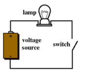
It's crucial to understand the fundamental components of an electric circuit. A source, a switch, a load, and a conductor make up a simple electric circuit. The following are the functions of these parts:

  1. The term "cell" refers to a device that is used to supply electric current.
  2. It's a resistor as a load. It may be a light bulb that illuminates when the electronic circuit is activated.
  3. Conductors: Copper wires with no insulation are used as conductors. The wire transfers current from the power source to the load on one end and from the load to the power source on the other.
  4. Switch: A switch is a component of an electronic circuit that regulates the flow of current through it. Its purpose is to close or open the electronic circuit.
NEET Highest Scoring Chapters & Topics
This ebook serves as a valuable study guide for NEET exams, specifically designed to assist students in light of recent changes and the removal of certain topics from the NEET exam.
Download E-book

The two basic properties of an electric circuit are current and voltage. The method of determining current and voltage in any element of an electric circuit is known as electric circuit analysis.

Current I flows through the simple circuit as a result of the entire circuit being electric, and a potential drop of V volts is created across the resistor.

Also, read -

Electric Circuit Symbols

Every part and product of an electric circuit has a symbol. Given below are the symbols of the parts that are present in an electric circuit.

electric circuit symbols

Electric circuits Types

Electric circuits are divided into two categories.

  1. Series circuit
  2. Parallel circuit

Series circuit-

There is only one way for electrons to flow in a series circuit. At the same time, the complete circuit is closed or open. The fundamental disadvantage of a series electric circuit project is that there is no current flow in all about circuits in the event of a circuit break because the entire power circuit is open. If several light bulbs are connected in a series circuit, for example, if one light bulb fails, the others will also fail.

Series Electrc circuit

Parallel circuit-

Distinct components of the circuit are connected across different branches in a parallel form of an electric circuit model. As a result, electron flow happens in multiple stages. If a circuit break occurs in one path, the electric current continues to flow in other paths. Parallel circuits are used in household appliance wiring, so if one light bulb goes out, the other will continue to work.

Parallel Electric circuit

Electric Circuit Formula

QuantityFormulaNotations
Electric current$I=\frac{Q}{t}$

I is the current, $t$ is the time period, $R$ is the resistance

Resistance$R=\rho \cdot \frac{L}{A}$

R is the resistance, $\rho$ is the resistivity value of the wire L is the length of the wire A is the cross-sectional area

Voltage$\Delta V=I . R$

$\Delta \mathrm{V}$ is the electric potential difference

Power$P=\frac{\Delta E}{t}$

$P$ is the power
$\Delta \mathrm{E}$ is the energy gain or loss, $t$ is the time period

Series circuit$R_{e q}=R_1+R_2+R_3+\ldots$

Req is the total resistance of the resistors placed in series, $\mathrm{R}_{\mathrm{l}}, \mathrm{R}_{2 \ldots}$ are the resistors placed in series

Parallel circuit$\frac{1}{R_{e q}}=\frac{1}{R_1}+\frac{1}{R_2}+\frac{1}{R_3}+\ldots$

Req is the total resistance of the resistors placed in parallel $\mathrm{R}_{\mathrm{l}}, \mathrm{R}_2 \ldots$ are the resistors placed in parallel

Domestic Electric Circuit Model

  1. The main supply, sometimes known as mains, provides the electricity that we receive in our homes.
  2. It can be provided by either overhead or underground wires.
  3. In residential circuits, there are three types of wires: Earth Wire, Live Wire, and Neutral Wire.
  • Earth Wire: Earth wire is usually a light green tint. It is linked to a metal plate placed in the ground near the house, which ensures the protection of metallic-bodied gadgets and appliances. To avoid shocks and damage, when a charge leak occurs in the metallic body, the charges are transported to the ground.
  • The positive conductor or wire, which is usually red in colour, is known as the live wire.
  • The negative conductor or wire, which is usually black in colour, is known as the neutral wire.
  1. In our country, the potential difference (or voltage) is delivered at 220V.
  2. Our house's electric current initially passes through a circuit known as a fuse. The fuse melts if there is a high voltage, overloading, voltage fluctuation, or short circuit, limiting the current supply and preventing the high voltage from reaching the electric appliances.
  3. The meter board distributes these cables to various electric appliances throughout the house.
  4. For domestic use, there are two types of electric circuits:
  • 15 A: Appliances have a greater wattage rating. (such as geysers, air conditioners, and refrigerators)
  • 5 A: Appliances with lower wattage ratings. (such as televisions, fans, and light bulbs)

Precautions From Electric Circuit

  1. For domestic wiring, always use high-quality wires with adequate insulation and thickness. Install ISI-marked products such as plugs, switches, and sockets to get the most out of your electrical appliances.
  2. The wire connections should be secure and thoroughly insulated.
  3. Before beginning any electrical circuit repair work, you should always turn off the main supply.
  4. Switch off the mains supply first if a short circuit or shock occurs. Then try to completely isolate the person who has been shocked by electricity. Do not come into immediate contact with him.
  5. Take measures when earthing or installing a fuse for the domestic electric circuits.

Frequently Asked Questions (FAQs)

1. What are the two different kinds of electric circuits?

Electric circuits Types


Series and parallel circuits are the two types of circuits commonly seen in homes and other common devices.

2. What does an electric circuit look like?

A connection of components that may conduct electric current is known as an electric circuit. Every circuit is made to supply electricity to one or more loads. The electricity of a boombox, for example, flows to the speakers. Similarly, the light bulb receives power from a lamp.

3. In the residence, what kind of circuit is used?

The majority of domestic circuits are (or should be) parallel circuits. Outlets, switches, and light fixtures are connected so that the hot and neutral wires maintain a continuous circuit pathway separate from the individual devices that use the circuit.

4. Is it safer to work in series or parallel?

Both of them can be equally safe. The decisive factor is the supply voltage. Parallel circuits have components that operate at equal voltages.

5. What are the drawbacks of a series circuit?

The first disadvantage is that if one component in a series circuit fails, the circuit as a whole fails because the circuit is broken. The second drawback is that the resistance of a series circuit increases as the number of components increases.

6. What is an electric circuit?
An electric circuit is a closed path that allows electric current to flow through it. It consists of a power source (like a battery), conducting wires, and one or more electrical components (such as resistors, capacitors, or light bulbs). The circuit provides a complete loop for electrons to move from the negative terminal of the power source, through the components, and back to the positive terminal.
7. How does current flow in a circuit?
Current in a circuit flows from the negative terminal of the power source to the positive terminal. This flow of current is actually the movement of electrons, which are negatively charged particles. Electrons move from areas of high potential energy (negative terminal) to areas of low potential energy (positive terminal). It's important to note that while electrons physically move from negative to positive, the conventional current direction is defined as flowing from positive to negative.
8. Why don't birds get electrocuted when sitting on power lines?
Birds don't get electrocuted when sitting on power lines because they're not part of a complete circuit. Electricity always seeks the path of least resistance to the ground. When a bird is perched on a single wire, it's at the same electrical potential as the wire, so current doesn't flow through its body. However, if the bird were to touch another wire with a different potential or a grounded object simultaneously, it would complete a circuit and could be electrocuted.
9. What is a short circuit?
A short circuit occurs when there's an unintended path of low resistance in an electric circuit, allowing current to flow directly from the power source back to itself without passing through the intended components. This can result in excessive current flow, potentially causing overheating, fire, or damage to the circuit components. Short circuits often happen when bare wires touch each other or when there's a fault in an electrical device.
10. What's the difference between AC and DC circuits?
AC (Alternating Current) and DC (Direct Current) circuits differ in the way current flows through them. In a DC circuit, current flows in one direction only, from the negative terminal to the positive terminal of the power source. In an AC circuit, the current periodically reverses direction, typically 50 or 60 times per second in household electricity. AC is commonly used in power grids and household appliances, while DC is used in batteries and many electronic devices.
11. Why do batteries eventually die?
Batteries "die" because of the chemical reactions that occur inside them. A battery produces electricity through a chemical reaction that transfers electrons from one material (the anode) to another (the cathode). As this reaction progresses, the chemicals are gradually consumed or converted into different forms. Eventually, the battery can no longer produce enough electrons to generate a useful electric current. This process is usually irreversible in disposable batteries, while rechargeable batteries can have this process reversed to some extent by applying an external current.
12. How do dimmer switches work?
Dimmer switches work by reducing the amount of electrical power delivered to a light bulb. Modern dimmers use a component called a TRIAC (Triode for Alternating Current) to rapidly switch the current on and off many times per second. By varying the proportion of "on" time to "off" time, the dimmer controls the average power delivered to the bulb. This rapid switching happens faster than the human eye can detect, so we perceive it as a smooth dimming effect. The dimmer essentially "chops" the AC waveform, reducing the overall power without simply lowering the voltage.
13. What is the purpose of a ground wire in electrical systems?
The ground wire in electrical systems serves as a safety feature. Its primary purpose is to provide a safe path for excess electrical current to dissipate into the earth, preventing electric shock or fire. If there's a fault in an appliance or if a live wire comes into contact with a metal casing, the ground wire provides a low-resistance path for the current to flow directly to the ground instead of through a person who might touch the appliance. This helps to trip circuit breakers or blow fuses quickly, cutting off the power supply and preventing potential accidents.
14. How do circuit breakers differ from fuses?
Circuit breakers and fuses both protect circuits from overcurrent, but they operate differently:
15. What is Kirchhoff's Current Law, and why is it important?
Kirchhoff's Current Law (KCL) states that the total current entering a junction (or node) in an electrical circuit is equal to the total current leaving that junction. In other words, the algebraic sum of currents in a network of conductors meeting at a point is zero. This law is based on the principle of conservation of electric charge and is crucial for analyzing complex circuits. It allows engineers and physicists to determine unknown currents in circuit branches and is fundamental to circuit analysis and design.
16. How does a capacitor store and release energy in a circuit?
A capacitor stores energy in an electric field between two conductive plates separated by an insulating material (dielectric). When connected to a power source, electrons accumulate on one plate, creating a negative charge, while the other plate becomes positively charged as electrons are repelled. This separation of charge stores electrical energy. When the power source is removed and the capacitor is connected to a circuit, it releases this stored energy as current flows from the negative plate to the positive plate until the charges equalize. Capacitors can rapidly charge and discharge, making them useful for smoothing voltage fluctuations and timing circuits.
17. How do transformers work, and why are they important in power distribution?
Transformers work on the principle of electromagnetic induction. They consist of two or more coils of wire wound around a common iron core. When an alternating current flows through one coil (the primary), it creates a changing magnetic field. This changing field induces a voltage in the other coil (the secondary). By varying the number of turns in each coil, transformers can increase (step up) or decrease (step down) voltage.
18. What is the purpose of a diode in an electric circuit?
A diode is a semiconductor device that allows current to flow in one direction while blocking it in the opposite direction. Its main purposes in electric circuits include:
19. What is the function of an inductor in a circuit?
An inductor is a passive electronic component that stores energy in a magnetic field when electric current flows through it. Its primary functions in a circuit include:
20. How do semiconductors differ from conductors and insulators?
Semiconductors occupy a unique position between conductors and insulators in terms of their electrical properties:
21. What is the purpose of a transistor in an electric circuit?
A transistor is a semiconductor device that serves several crucial purposes in electric circuits:
22. How does a thermocouple generate electricity?
A thermocouple generates electricity through the Seebeck effect, a phenomenon where a temperature difference between two dissimilar electrical conductors or semiconductors produces a voltage difference between the two substances. Here's how it works:
23. What is the difference between analog and digital circuits?
Analog and digital circuits differ in how they process and represent information:
24. How does a solar cell convert light into electricity?
A solar cell, also known as a photovoltaic cell, converts light energy into electrical energy through the photovoltaic effect. Here's how it works:
25. What is the function of a rectifier in an electric circuit?
A rectifier is a device or circuit that converts alternating current (AC) to direct current (DC). Its primary functions are:
26. How does a fuse protect an electric circuit?
A fuse protects an electric circuit by acting as a sacrificial device. It contains a thin wire or strip of metal that's designed to melt when too much current flows through it. If there's a fault in the circuit causing excessive current (like a short circuit), the fuse will "blow" or melt, breaking the circuit and stopping the flow of electricity. This prevents damage to other components in the circuit or potential fire hazards. Once a fuse blows, it needs to be replaced to restore the circuit's functionality.
27. What's the difference between series and parallel circuits?
Series and parallel circuits differ in how components are connected:
28. How does a light switch work in a circuit?
A light switch works by controlling the flow of current in a circuit. In its simplest form, a switch is a device that can make or break an electrical circuit. When the switch is in the "on" position, it closes the circuit, allowing current to flow through the light bulb or fixture. When the switch is in the "off" position, it opens the circuit, creating a gap that prevents current from flowing. This simple mechanism allows us to easily control electrical devices by interrupting the path of the current.
29. What is electrical resistance, and how does it affect a circuit?
Electrical resistance is a material's opposition to the flow of electric current. It's measured in ohms (Ω). In a circuit, resistance affects the amount of current that can flow for a given voltage. According to Ohm's Law, current (I) is equal to voltage (V) divided by resistance (R): I = V/R. Higher resistance results in less current flow, while lower resistance allows more current to flow. Resistance also causes electrical energy to be converted into heat, which is why electrical components can warm up during use.
30. What is the difference between voltage, current, and power in a circuit?
Voltage, current, and power are related but distinct concepts in electrical circuits:
31. How does Ohm's Law relate voltage, current, and resistance?
Ohm's Law is a fundamental principle in electrical engineering that describes the relationship between voltage (V), current (I), and resistance (R) in an electrical circuit. The law states that the current through a conductor between two points is directly proportional to the voltage across the two points and inversely proportional to the resistance between them. Mathematically, it's expressed as:
Meter Bridge

04 Jul'25 02:56 PM

Mobility Of Electron

02 Jul'25 07:59 PM

Galvanometer

02 Jul'25 07:02 PM

Thermo Couple

02 Jul'25 05:52 PM

Emf Of A Cell

02 Jul'25 05:52 PM

Current Given by a Cell

02 Jul'25 05:51 PM

Articles

Back to top