

To Find Resistance Of A Given Wire Using Metre Bridge And Hence Determine The Specific Resistance
A metre bridge, also called a slide-wire bridge, is a device based on the principle of the Wheatstone bridge. It is commonly used in physics labs to find the unknown resistance of a wire and to determine the resistivity of its material. This experiment is one of the most important practicals in electricity because it teaches how resistance can be measured accurately by balancing the two arms of the bridge. Understanding resistance is essential in real life, as it affects the design of electrical circuits, safety systems, fuses, household wiring, and the performance of batteries and devices. By performing this experiment, students learn how electrical resistance works and why precise measurement is important in technology and engineering.
This Story also Contains
- To Find the Resistance Of A Given Wire Using the Metre Bridge
- Aim of the Meter Bridge Experiment
- Apparatus Required for Meter Bridge Experiment
- Theory of Meter Bridge Experiment
- Circuit Diagram of Meter Bridge
- Procedure for Meter Bridge Experiment
- Calculation of Meter Bridge Experiment
- Result of Meter Bridge Experiment
- Precautions of the Meter Bridge Experiment
- Metre Bridge Experiment Viva Questions
- Solved Examples Based on Finding the Resistance of a Given Wire Using a Metre Bridge
To Find the Resistance Of A Given Wire Using the Metre Bridge
Below, we have given the meter bridge experiment process in which the aim, apparatus required, procedure and observation of the Meter Bridge experiment are given.
Aim of the Meter Bridge Experiment
To find the resistance of a given wire using a meter bridge and hence determine the resistivity (specific resistance) of its material.
Apparatus Required for Meter Bridge Experiment
- A meter bridge
- A Leclanché cell (or battery eliminator)
- A galvanometer
- A resistance box
- A jockey
- A one-way key
- A resistance wire
- A screw gauge
- A meter scale
- A set square
- Connecting wires
- A piece of sandpaper
Theory of Meter Bridge Experiment
(i) The unknown resistance X is given by $X=\frac{(100-l)}{l} \cdot R$
where,
R is the known resistance placed in the left gap, and the unknown resistance X is in the right gap of the meter bridge. $l \mathrm{~cm}$ is the length of the meter bridge wire from zero ends up to the balance point.
(ii) Specific resistance $(\rho)$ of the material of the given wire is given by $\rho=\frac{X \pi D^2}{4 L}$
where,
L is the length and D is the diameter of the given wire.
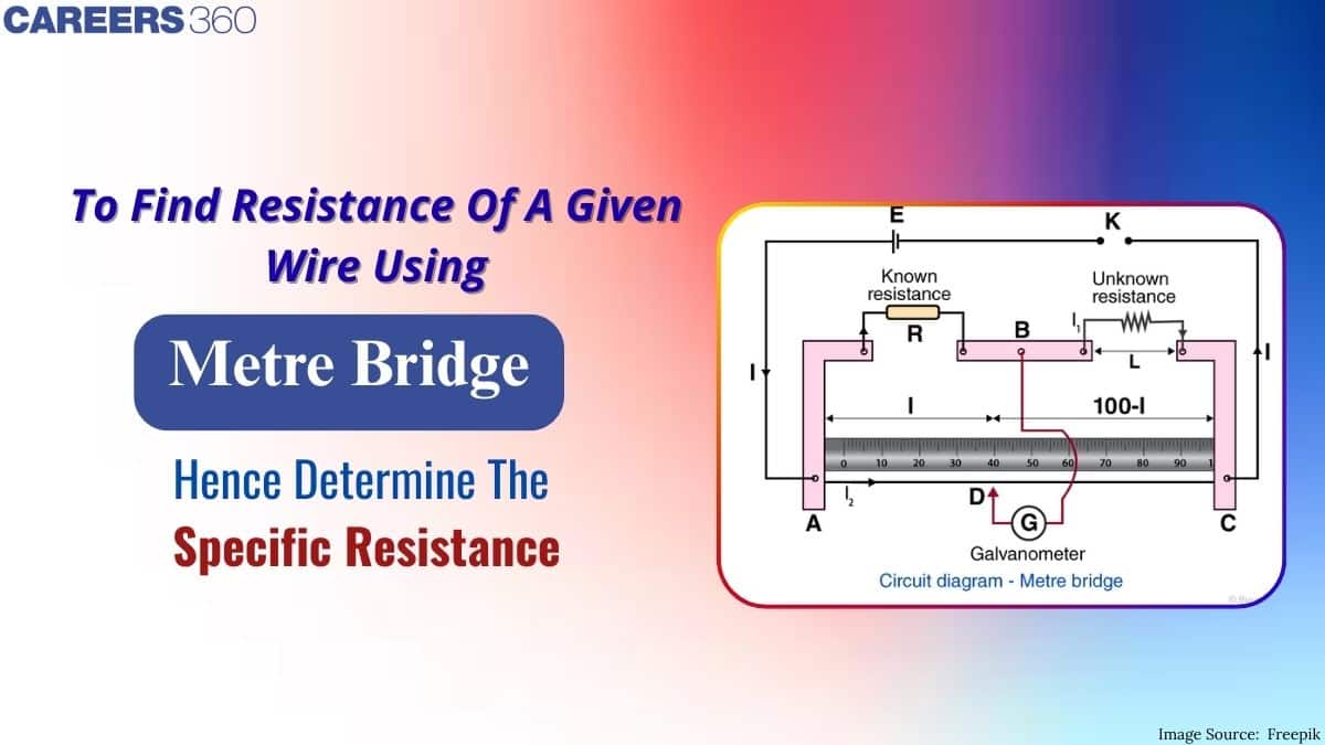
Circuit Diagram of Meter Bridge

Procedure for Meter Bridge Experiment
For Resistance
1. Arrange the apparatus as shown in the arrangement diagram.
2. Connect the resistance wire whose resistance is to be determined in the right gap between C and B.
Take care that no part of the wire forms a loop:
3. Connect the resistance box of low range in the left-hand gap between A and B.
4. Make all the other connections as shown in the circuit diagram.
5. Take out some resistance (say 2 ohms) from the resistance box, and plug the key K.
6. Touch the jockey gently first at the left end and then at the right end of the bridge wire.
7. Note the deflections in the galvanometer. If the galvanometer shows deflections in opposite
directions, the connections are correct. If the deflection is on one side only, there is some fault in the
circuit. Check or take the help of your teacher and rectify the fault.
8. Move (slide) the jockey gently along the wire from left to right till the galvanometer gives zero deflection. The point where the jockey is touching the wire is null point D.
9. Choose an appropriate value of R from the resistance box such that there is no deflection in the
galvanometer when the jockey is nearly in the middle of the wire (i.e. between 45 cm to 55 cm ).
10. Note the position of the point with the help of a set square. to know the length $A D=l$
11. Take at least four sets of observations in the same way by changing the value of R in steps.
12. Record your observations.
For Specific Resistance
13. Cut the resistance wire at the points where it leaves the terminals, stretch it and find its length by using a meter scale.
14. Measure the diameter of the wire at least at four places, in two mutually perpendicular directions at each place with the help of a screw gauge.
15. Record your observations as given in the tables.
Calculation of Meter Bridge Experiment
I. Calculation for $X$
1. From the position of D, find $l \mathrm{~cm}$
2. Similarly, Find the length $(10 \overline{0}-\mathrm{l}) \mathrm{cm}$
3. Calculate $X$ and find
$
\text { Mean } X=\frac{X_1+X_2+X_3+X_4}{4}$= ohm
II. Calculation for D
$
\begin{aligned}
\text { Mean corrected diameter } & =\frac{D_1(a)+D_1(b)+\ldots \ldots+D_4(a)+D_4(b)}{8} \\
& =\ldots \ldots \mathrm{mm}=\ldots \ldots \mathrm{cm}
\end{aligned}
$
III. The calculation for Specific Resistance
The specific resistance of the material of the given wire,
$
\begin{aligned}
& \rho=\frac{X \pi D^2}{4 L} \\
& \rho=\ldots \ldots . \text { ohm }-\mathrm{cm} \\
& \rho=\ldots \ldots \text { ohm }-\mathrm{m}
\end{aligned}
$
The standard value of the specific resistance of the material of the given wire (if given) $\rho_0=\ldots \ldots$ ohm -m
percentage error $=\frac{\rho-\rho_0}{\rho_0} * 100=$ $\qquad$ $\%$
Result of Meter Bridge Experiment
1. The value of unknown resistance X=...
2. The specific resistance of the material of the given wire = ......
3. Percentage error =
Precautions of the Meter Bridge Experiment
1. The connections should be neat, clean and tight.
2. All the plugs in the resistance box should be tight.
3. The null point should be brought between 45 cm and 55 cm.
4. The wire should not make a loop.
Sources of Error
1. The instrument screws may be loose.
2. The plugs may not be clean.
3. The wire may not have a uniform thickness.
4. The screw gauge may have faults like backlash errors and wrong pitch.
Metre Bridge Experiment Viva Questions
Q1. Why is the metre bridge called so?
Ans: It is called a metre bridge because it uses a resistance wire that is exactly one metre long.
Q2. What is the null point?
Ans: The null point is the position on the wire where the galvanometer shows zero deflection, meaning both sides of the bridge are balanced.
Q3. Why is the bridge method better than using Ohm’s law for measurement?
Ans: The bridge method is more accurate because it uses a null method, in which no current flows through the galvanometer at balance. This reduces errors.
Q4. What is the range of resistance that can be measured using a Wheatstone bridge?
Ans: A Wheatstone bridge can measure resistances from about 1 Ω to several megaohms.
Q5. How can a Wheatstone bridge be used to measure physical parameters?
Ans: A Wheatstone bridge can measure physical quantities like temperature, light, pressure, or strain when the resistances in the bridge are connected to sensors. Operational amplifiers and rectifiers are used for accurate readings and AC–DC conversion.
Also Check-
Solved Examples Based on Finding the Resistance of a Given Wire Using a Metre Bridge
Example 1: In a meter bridge experiment null point is obtained at 40 cm from one end of the wire when resistance X is balanced against another resistance Y. If $X<Y$, then the new position (in cm) of the null point from the same end, if one decided to balance a resistance of 3X against Y, will be close to : (in cm)
1) 67
2) 75
3) 80
4) 50
Solution:
We have from the meter bridge experiment
$\frac{R_1}{R_2}=\frac{l_1}{l_2}$ where $l_2=\left(100-l_1 \mathrm{~cm}\right)$
In the first case, $\frac{X}{Y}=\frac{20}{80}$
In the second case, $\frac{3 X}{Y}=\frac{l}{100-l}$ $l=67 \mathrm{~cm}$
Hence, the answer is the option (1).
Example 2: A student wants to determine the resistivity of the material of a given wire using a meter bridge experiment. The wire is placed on the meter bridge, and various measurements are taken to calculate the resistivity. The known resistors are connected in a ratio of 1: 9 on one side of the meter bridge. The student balances the bridge by sliding the jockey along the wire. The length of the wire between the jockey and the point of balance is measured to be L = 80 cm. The length of the wire between the jockey and the known resistors is 100 cm, and the known resistance is R = 10 Ω. Calculate the resistivity (ρ) of the material of the given wire.
1) 5.81 ×10⁻⁷ Ω · m
2) 68.9 ×10⁻⁷ Ω · m
3) 5.45 ×10⁻⁷ Ω · m
4) 9.81 ×10⁻⁷ Ω · m
Solution:
Given data:
Length of wire between jockey and balance point (L) = 80cm = 0.80 m
Length of wire between jockey and known resistors = 100 cm = 1.00 m , Known resistance (R) = 10 Ω
Using the principle of the meter bridge experiment, the ratio of resistances is equal to the ratio of lengths:
$
\frac{R}{\text { Unkown resistance }}=\frac{\text { Length of wire with known resistance }}{\text { Length of wire with unknown resistance }}
$
Substituting the given values:
$
\frac{10}{\text { Unkownresistance }}=\frac{1.00}{0.80}
$
Solving for the unknown resistance:
$
\text { Unkownresistance }=\frac{10 \times 0.80}{1.00}=8 \Omega
$
Now, we can use the formula for resistivity:
$
\rho=\frac{R \times A}{L}
$
Where A is the cross-sectional area of the wire. Let's assume the wire's diameter $(\mathrm{d})$ is $0.1 \mathrm{~cm}(0.001 \mathrm{~m})$. Therefore, radius $(\mathrm{r})=0.0005 \mathrm{~m}$. The cross-sectional area $(\mathrm{A})$ is $\pi \mathrm{r}^2$ :
$
A=\Pi \times(0.0005)^2=7.85 \times 10^{-7} \mathrm{~m}^2
$
Now, substituting the values into the resistivity formula:
$
\rho=\frac{10 \times 7.85 \times 10^{-7}}{0.80}=9.81 \times 10^{-7} \Omega m
$
Therefore, the resistivity (ρ) of the material of the given wire is $9.81 \times 10^{-7} \Omega m$.
Hence, the answer is the option (4).
Example 3: An electrical circuit consists of three resistors R1, R2, and R3 connected in a combination of series and parallel. The circuit is powered by a constant voltage source of 48V. The currents flowing through each resistor are measured and recorded:
| Resistor | Current (A) |
| R1 | 2.0 |
| R2 | 1.5 |
| R3 | 3.0 |
Using this data, calculate the equivalent resistance of the entire circuit:
Solution:
In a circuit with a combination of series and parallel resistors, you need to first determine the equivalent resistance of the individual series and parallel segments before calculating the overall equivalent resistance.
For the parallel segment (Rp), the reciprocal of the total resistance (1/Rp, eq) is the sum of the reciprocals of the individual resistances:
$
\frac{1}{R_{p, e q}}=\frac{1}{R_2}+\frac{1}{R_3}
$
Now, calculate $R_{p, \text { eq }}$ :
$
R_{p, e q}=\frac{1}{\frac{1}{R_2}+\frac{1}{R_3}}=\frac{1}{\frac{1}{1.5}+\frac{1}{3}}=1.0 \Omega
$
Now, the total equivalent resistance $\left(R_{\text {eq }}\right)$ is the sum of the series resistance $\left(R_1\right)$ and the parallel equivalent resistance $\left(R_{p \text {, eq }}\right)$ :
$
R_{e q}=R_1+R_{p, e q}=2.0+1.0=3.0 \Omega
$
Hence, the equivalent resistance of the entire circuit is $3.0 \Omega$.
Hence, the answer is the option (4).
Example 4: A student wants to determine the resistivity of the material of a given wire using a meter bridge. The known resistance used in the experiment is 10 Ω. The wire is stretched along the length of the meter bridge. When a balance point is obtained, the length of the wire on the bridge is found to be 60 cm. The length of the bridge wire is 100 cm, and its resistance is negligible. Calculate the resistivity of the material of the given wire.
1) 6πr2 Ω · m
2) 38πr2 Ω · m
3) 87 πr2 Ω · m
4) 16πr2 Ω · m
Solution:
Given data: Known resistance, R1 = 10 Ω
Length of wire on the bridge, l1 = 60 cm = 0.6 m
Length of the bridge wire, L = 100 cm = 1 m
Let’s assume the resistivity of the given wire material is ρ.
At balance, the ratio of the lengths of the wire on the bridge to the length of the bridge wire is equal to the ratio of resistances:
$\frac{l_1}{L}=\frac{R_1}{R}$
We want to find ρ, so we need to express R in terms of ρ and other given
quantities.
Resistance of the wire, R = ρ·l1/A
Where A is the cross-sectional area of the wire. Since the wire is uniform, its cross-sectional area remains constant.
Now we can substitute the expression for R into the balance equation:
$\begin{aligned} & \frac{l_1}{L}=\frac{R_1}{R} \\ & \frac{l_1}{L}=\frac{R_1 \cdot A}{\rho \cdot l_1} \\ & \rho=\frac{R_1 \cdot A \cdot l_1}{l_1 / L}\end{aligned}$
Now we need to find the value of A, the cross-sectional area of the wire.
Let’s assume the wire is cylindrical in shape with radius r. The cross-sectional area of a cylinder is given by:
$
A=\pi \cdot r^2
$
We can substitute this into the expression for $p$ :
$
\rho=\frac{R_1 \cdot \Pi^2 \cdot r^2 \cdot l_1}{l_1 / L}
$
Given that $\mathrm{L}=1 \mathrm{~m}, \mathrm{I}=0.6 \mathrm{~m}$, and $\mathrm{R} 1=10 \Omega$, we can rearrange the equation to solve for $\rho$ :
$
\begin{aligned}
& \rho=\frac{10 . \Pi \cdot r^2 \cdot 0.6}{1 / 1} \\
& \rho=6 \pi r^2 \Omega \cdot m
\end{aligned}
$
The resistivity of the material of the given wire is given by ρ = 6πr2 Ω·m. Please note that the above calculation assumes that the wire is a uniform cylinder and that the length is stretched along the meter bridge with a balance point. In practice, other factors like temperature variations and non-uniformity of the wire might affect the accuracy of the result.
Hence, the answer is the option (1).
Example 5: In a laboratory experiment, a meter bridge setup is used to determine the resistivity of an unknown material of a given wire. The setup consists of a uniform wire of length 1.5 meters, which is placed horizontally on a non-conductive table. A jockey is used to make electrical contact along the length of the wire. The bridge is balanced using a standard resistor of known resistance 10 ohms. The resistivity of the material is to be calculated.
Given the following additional information:
- Length of the wire (l): 1.5 meters
- Length of the wire segment to the left of the jockey (x): 0.75 meters
- Length of the wire segment to the right of the jockey (l − x): 0.75 meters
- Known resistance (R1): 10 ohms
The bridge is balanced when the null point is achieved, where the jockey is placed at a specific position on the wire. Using the above data and the principles of the meter bridge experiment, calculate the resistivity (ρ) of the unknown material of the wire. Express your answer in terms of fundamental constants and known quantities.
Solution:
1. We know that the resistance of a wire is given by the formula $R=\rho\left(\frac{l}{A}\right)$ where ρ is the resistivity of the material, l is the length of the wire, and A is the cross-sectional area of the wire.
2. In the case of the meter bridge experiment, we have a uniform wire of length l = 1.5 meters. The cross-sectional area (A) of the wire is uniform throughout its length.
3. Let's consider a unit length of the wire (1 meter) for ease of calculation. Therefore, the resistance $R$ of this unit length of wire is given by:
$
R=\rho\left(\frac{l}{A}\right)
$
4. The bridge is balanced when the ratio of the resistances on the two sides of the jockey is equal to the ratio of the lengths of the wire segments: $\frac{R_1}{R_2}=\frac{x}{l-x}$.
5. Substituting the values: $\frac{10}{R_2}=\frac{0.75}{0.75}$
6. Solving for $R_2$, we find: $R_2=10$ ohms.
7. Now we can substitute the value of R2 into the resistance formula for the unit length of the wire:
$
\rho\left(\frac{1}{A}\right)=10
$
8. Rearranging the formula to solve for $\rho$, we get $\rho=10 A$.
10. The radius of the wire is not provided directly, but we can express it in terms of the length of the wire ( 1 ) and the unknown resistivity ( $\rho$ ):
$
r=\sqrt{\frac{\rho l}{\pi}}
$
11. Substituting this value of $r$ back into the formula for the cross-sectional area:
$
A=\pi\left(\sqrt{\frac{\rho l}{\pi}}\right)^2=\frac{\rho l}{\pi}
$
12. Substituting the value of $A$ back into the resistivity formula:
$
\rho=10\left(\frac{\rho l}{\pi}\right)
$
13. Solving for $\rho: \rho=10\left(\frac{\rho 1.5}{\pi}\right)$.
14. Simplifying: $\rho=\frac{15 \rho}{\pi}$.
15. Finally, solving for $\rho: \rho=\frac{15}{\pi}$ ohm meter.
16. Approximating the value of $\pi$ as 3.14 , we get $\rho \approx 4.77$-ohm meter.
Therefore, the resistivity of the unknown material of the wire is approximately 4.77 ohm meter.
Hence, the answer is the option (1).
An attempt to measure the resistance of a given wire using a meter bridge would consist of pushing the sliding contact on one of the wires, exactly one meter, into the circuit until a balance is attained. The length at which the balancing is obtained will be noted along with the known resistances, from which the unknown resistance of that wire may be calculated. According to Marks and Spencer, it is a very good way to do the experiment, namely, to learn about material properties and how they relate to electrical engineering contrivances, quite like some of whatever we use daily.
Releated Links-
Frequently Asked Questions (FAQs)
The bridge method is more accurate because it uses a null or zero-current condition, which avoids errors due to resistance of connecting wires, heating effects, or fluctuations in the power source.
The null point allows us to achieve a condition of balance in the Wheatstone bridge, where no current flows through the galvanometer, giving the most accurate value of resistance.
A jockey is used to slide over the wire and make electrical contact at different points to find the null point accurately.
The wire is one metre long to allow easy measurement and calculation of resistance, since the bridge works on the proportionality of resistance and length.
A metre bridge works on the principle of the Wheatstone bridge, where the ratio of resistances in one arm is compared with the ratio in the other arm to find an unknown resistance.
